Pre Engineered Steel Structure Detail
The Steel Structure detail outlines the specifications of the rigid frame, multi-floor frame, and truss structure, which are the most commonly used building structures for warehouses, workshops, multi-floor buildings, venues, stations, and Aircraft Hangars. These structures provide a robust and reliable foundation for a variety of applications.
Table of Contents
1.What is the Steel structure?
2.Steel Specification
3.Steel Structure Detail for Rigid Frame Structure:
3.1.Length and Width of Steel Building :
3.2.Column Distance
3.3.Determination of a reasonable span
3.4.Steel Structure Detail-Roof slope
3.5.Steel Structure detail: Height
3.6.Steel Structure Detail-Bracing
3.7.Stee Structure Detail-Basic principles of bracing settings
3.7.1.In the following situations, the installation of vertical-horizontal roof bracing needs to be considered.
3.7.2.In the following cases, the column bracing needs to be layered.
3.7.2.1.Round steel, angle steel, or round (square) pipe can be used for Column Cross Bracing.
3.8.Steel Structure detail – use and setting of the flange bracing.
4.Steel Structure detail for Multi-floor Steel Frame Structure
4.1.Connection Type for Steel Frame Structure
5.Steel Structure Detail for Truss Structure
5.1.1. Angle Steel Truss
5.2.2. Steel pipe truss:
5.3.3. H-shaped steel truss:
5.4.4. Box-shape steel truss:
6.Steel Structure Design
6.1.Steel structure design should include the following contents:
7.Steel structure design standards in different countries:
7.1.Basic principles of steel structure design
7.1.1.Steel structure design requires reasonable component selection based on the project’s needs and load requirements.
7.1.2.Load calculation is an indispensable part of steel structure design.
7.1.3.Connection design is also a crucial part of steel structure design.
8.Features of steel structure:
8.1.1. Save steel consumption and save investment
9.Prevent leakage; the effect is ideal
9.1.3.No piling required, shortening the construction period
9.2.4.Fast delivery and easy installation
9.3.5.The appearance is beautiful, and the interior is empty
Steel structures are composed of steel materials and are one of the main types of building structures. Beams, columns, trusses, and other components are usually made of section steel and plates and use rust removal and anti-rust processes such as spray painting or galvanizing. Welds, bolts, or rivets generally connect each element or component. These structures are lightweight, high-strength, fast construction, energy-saving, and reusable. They are widely used in high-rise buildings, factories, bridges, and other fields.
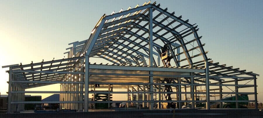
steel structure detail
Steel structure materials commonly used in different countries:
USA: ASTM A36, ASTM A572, ASTM A992, ASTM A514, ASTM A709, etc. Among them, ASTM A36 is one of the most commonly used low-carbon steel materials.
Europe: S235JR, S275JR, S355JR, S420MC, S460MC, etc. Among them, S355JR is one of the most commonly used structural steel materials.
China: Q235, Q355, Q420, Q460, Q690, etc. Q235B and Q355B are the most commonly used low-carbon steel materials.
Japan: SS400, SM490, SM520, SM570, etc. SS400 is one of the most commonly used structural steel materials.
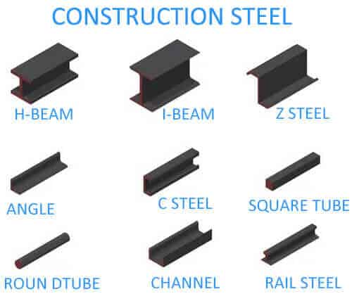
Construction steel
Many section steel types exist, including solid, long steel strips with specific cross-sectional shapes and sizes.
Angle steel
Angle steel, commonly known as angle iron, is a long strip of steel perpendicular to each other and forms an angle. There are equilateral angle steel and unequal angle steel. The two sides of an equilateral angle are equal in width. Its specifications are expressed in millimeters of side width x side width x side thickness. For example, “∠30×30×3” means equilateral angle steel with a side width of 30 mm and a side thickness of 3 mm.
Round steel
Round steel refers to a solid steel strip with a circular cross-section. Its specifications are expressed in millimeters of diameter.
Channel steel
Channel steel is a long strip of steel with a grooved cross-section.
Steel plate
It is a flat steel material with a large aspect ratio and surface area. According to the thickness, it can be divided into three types: thin plate (thickness<4mm), medium plate (thickness 4-25mm), and thick plate (thickness>25mm)
Steel pipe
It is a long strip of steel with a hollow section. According to its cross-sectional shape, it can be divided into round pipes, square pipes, hexagonal pipes,s, and various special-shaped cross-section steel pipes. According to different processing technologies, it can be separated into two categories: seamless steel pipe and welded pipe.
Steel Structure Detail for Rigid Frame Structure:
The rigid portal frame structure is a single-story building made of steel with interconnecting beams and columns. It boasts a straightforward design, lightweight components, and the added benefit of having all its elements prefabricated for easy on-site assembly. These features make it ideal for various structures, including industrial and commercial warehouses, workshops, storage facilities, poultry buildings, and aircraft hangars.
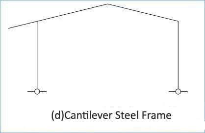
The rigid frame structures can be classified into various categories, including single-span (represented by Figure a), double-span (depicted by Figure b), multi-span (represented by Figure c), cantilever steel frame (depicted by Figure d), and steel frames with adjacent frames (represented by Figure e). The connection between the columns and roof beams in multi-span rigid frames follows a hinged pattern. Single-slope roofs (illustrated by Figure f) are a common feature in these structures.
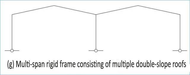
A multi-span rigid frame consisting of multiple double-slope roofs is viable (as seen in Figure G). The beam-column cross-section can be uniform or vary in size, and the columns can be either hinged or rigidly connected at the base.
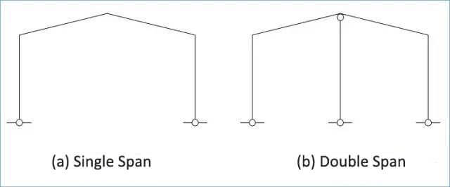
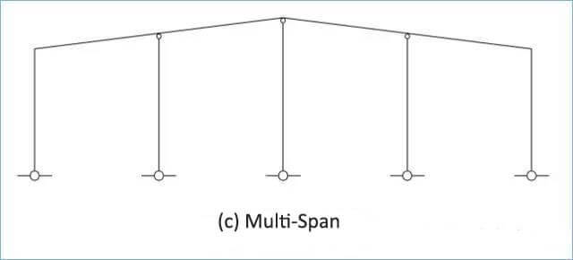

Steel Structure Detail
Length and Width of Steel Building :
Adhering to the general principle that the length exceeds the width, using steel in a rigid frame can be optimized, reducing steel requirements and creating a more efficient bracing system. This, in turn, reduces the overall metal consumption in the bracing system.
Example 1: The building’s size is 60x50m; 60 m should be used as the length and 50m as the width, that is, 60 (L) x 50 (W), not 50 (L) x 60 (W).
Column Distance
Standard loads’ most cost-effective column spacing is between 7.5 to 9 meters. Beyond 9 meters, the usage of steel in roof purlins and wall girts becomes excessive, leading to higher overall costs. The standard load referred to here includes a live roof load of 0.3 KN/m2 and essential wind pressure of 0.5 KN/m2. The optimal column spacing should be reduced if the load is more significant. In the case of workshop buildings equipped with cranes weighing more than 10 tons, the ideal column spacing should be between 6 to 7 meters for financial reasons.
For uneven column spacing, placing columns closer together at the end spans, where wind loads are more substantial than the center span, is recommended. Additionally, when utilizing a continuous purlin design, the end-span and mid-span tend to experience more significant deflection than other spans. By using smaller end-span column spacing, the design of the roof purlins becomes more manageable and cost-effective.
Example 1: Building length = 70m
Economical column distance is available: 1 @ 7 + 7 @ 8 + 1 @ 7 or 1 @ 8 + 6 @ 9 + 1 @ 8
Example 2: Building length = 130m, with a 10-ton crane
Economical column distance is preferable: 1 @ 5.5 + 17 @ 7 + 1 @ 5.5 or 20 @ 6.5
Determination of a reasonable span
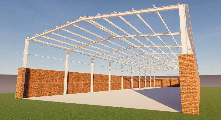
The span of a metal building is primarily determined by its intended use and production processes. Some owners may even request that the manufacturer determine a more economical span based on the specific requirements of the building. A reasonable span should be defined based on the height of the steel building. When the column height and load remain constant, increasing the span can save space, minimize foundation costs, and provide overall cost benefits despite a slight increase in steel consumption for the rigid frame.
steel structure detail
Calculations show that when the eaves height is 6 meters, the column spacing is 7.5 meters, and the load conditions are consistent, the steel consumption of the rigid frame (made of Q355B steel) ranges from 10-15 kg/m2 for widths between 18-30 meters. For rigid frame units between 21-48 meters, the steel consumption is 12-24 kg/m2. In cases where the eave’s height is 12 meters, and the width exceeds 48 meters, using a multi-span rigid frame with a sway column set in the middle can result in savings of over 40%. Therefore, choosing a more economical span based on specific requirements is recommended when designing a rigid portal structure rather than aiming for a large one.
Steel Structure Detail-Roof slope
The roof slope is determined based on several factors, including the roof structure, the slope length for drainage, and the height of the columns. Typically, roof slopes range from 1/10 to 1/30. Research has shown that different roof slopes significantly impact the amount of steel used in rigid steel frames. The following results are based on calculations and analysis of steel consumption under different roof slopes, with a single span of 42 meters and an eaves height of 6 meters.
The weight of a frame structure with a roof slope of 0.5:10 is 3682 kg, while that of a frame with a roof slope of 1:10 is 3466 kg. A frame with a roof slope of 1.5:10 weighs 3328 kg, and a roof slope of 2:10 weighs 3240 kg.
Therefore, for a single-span rigid frame, a way to reduce its weight is to increase the roof slope, as a larger slope means less steel is required. However, this does not hold for a multi-span frame. A steep slope will increase the metal used in the frame, resulting in a more extended inner column.
When the span of a building is substantial, increasing the incline can reduce the deflection of the roof steel beam. Based on research and calculations, the most economical slopes are as follows:
For multi-span buildings: 1:20
For single spans less than 45 meters: 0.5:10
For single spans less than 60 meters: 1.5:10
For single spans over 60 meters: 2:10
It’s worth noting that the presence of a parapet wall also influences the roof slope. A steep slope will increase the cost of the parapet wall.
Steel Structure detail: Height
The eave height plays a crucial role in determining the cost of a prefab steel building, affecting various aspects such as:
Increasing the eave height increases the wall cladding, wall girt, and steel usage for columns.
Without lateral bracing, the eave height has a more profound impact on the frame weight, resulting in increased wind load. If the height/building width ratio is above 0.8, changing the column foot from hinged to rigid may be necessary to control lateral displacement.
The eave height is determined by several factors, including:
Required height at the eave.
The net height of the mezzanine structure and the height of the mezzanine beam when present.
The height of the crane beam and crane hook when a crane is available.
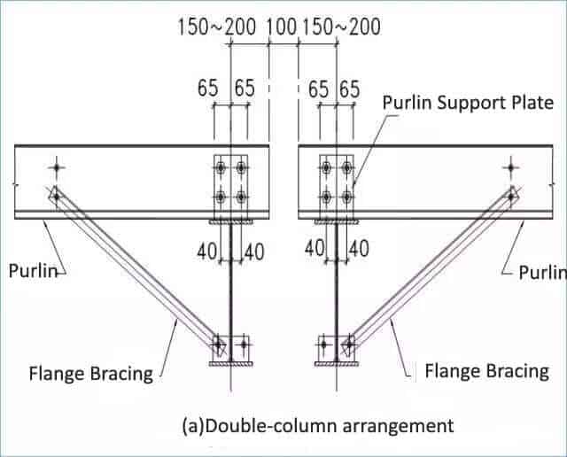
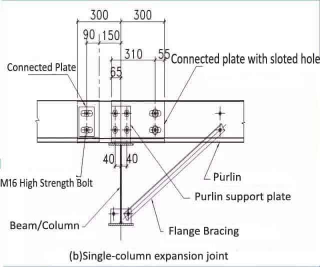
The temperature section of prefab steel buildings is subject to specific guidelines. The code stipulates that the maximum length of the building cannot exceed 300 meters, and its width must not exceed 150 meters. The building’s design determines the first temperature-segmented expansion joint’s placement. It can be arranged as a double-column setup (as illustrated in Figure a) or a single-column expansion joint with slotted holes connected to the purlin (Figure b).
Steel Structure Detail-Bracing
(A) The uses of the Bracing
The longitudinal structure of a portal frame is susceptible to instability in the length direction due to its weak stiffness. Installing bracing in the longitudinal direction is imperative to ensure its longitudinal stability. The bracing system must withstand various forces, including longitudinal wind loads, crane braking forces, earthquake forces, and temperature changes. When calculating the strength of the brace, the joints are typically treated as hinges, and the impact of eccentricity is ignored. The bracing system design considers the support provided by tie beams, making a two-way arrangement the preferred solution.
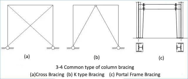
(B) Common types of bracing
Steel Structure detail
Stee Structure Detail-Basic principles of bracing settings
- Column bracing should be installed on the same span as the roof bracing. In cases where the door opening on the wall prevents this, the column bracing can be placed on the neighboring span.
- The distance between bracings should not exceed five spans. When no crane is available, a distance of 30 to 45 meters should be maintained. However, the distance should not exceed 60 meters when a crane is present.
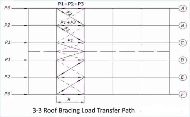
- The roof bracing should be divided along the ridge line (Figure 3-3).
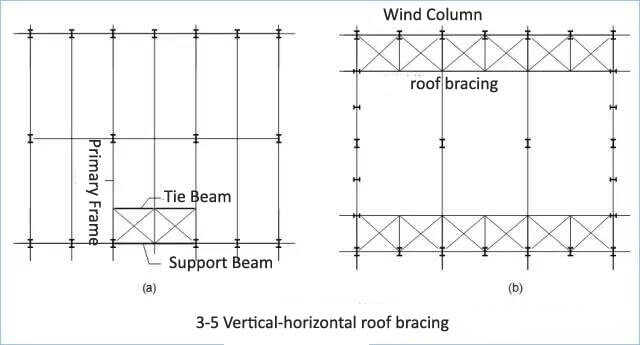
In the following situations, the installation of vertical-horizontal roof bracing needs to be considered.
- In the event of a removed column (when one or more columns are removed within the column network), longitudinal bracing will suffice, as depicted in Figure 3-5a.
- When the distance between columns is substantial, a false wall frame column may be used, as illustrated in Figure 3-5b.
- This will also be considered if the crane has a capacity of over 15 tons.
Steel Structure detail
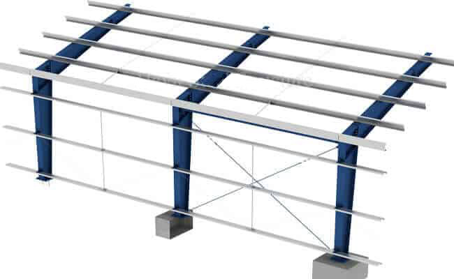
Wall Bracing
In the following cases, the column bracing needs to be layered.
2.Double-layer column bracing can be installed for structures with eave heights exceeding 9m, with the bracing angle included. The angle between the cross-bracing and the horizontal plane should be approximately 45° and not exceed 55°. The upper and lower bracing should be placed between columns. In end-opening rooms, it may be desirable to omit the lower bracing to reduce stress on the crane beam due to temperature changes, as shown in Figure 3-6b.
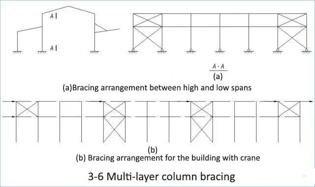
steel structure detail
Steel rod bracing is inadequate for column bracing subjected to significant internal forces or cranes with a lifting capacity exceeding 5 tons. In these scenarios, angle steel or round (square) pipes should be used as the column bracing material.
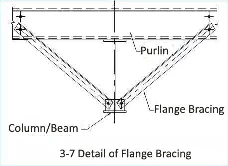
Steel Structure detail – use and setting of the flange bracing.
Steel Structure detail for Multi-floor Steel Frame Structure
The steel frame structure consists of frame beams, columns, beam-column connections, composite flooring made of profiled steel sheets, and a solid foundation.
The flooring system employs both primary and secondary beams and composite flooring. As a result, installing the steel floor deck, binding floor reinforcements, and concrete pouring must all be done on-site.
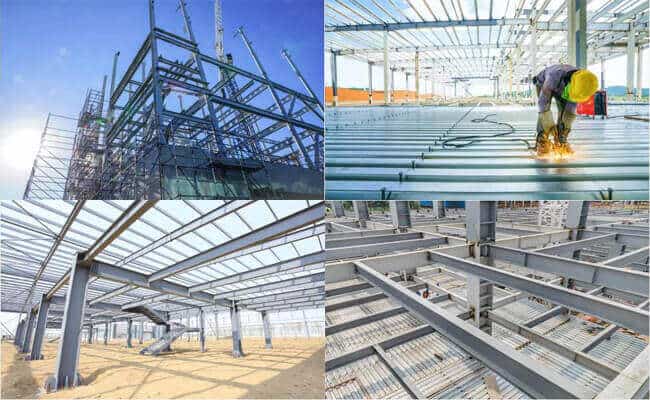
Steel Frame Structure
Connection Type for Steel Frame Structure
Node types mainly include beam-to-column, beam-to-beam, column-to-column, and connection nodes at the foot of a column.
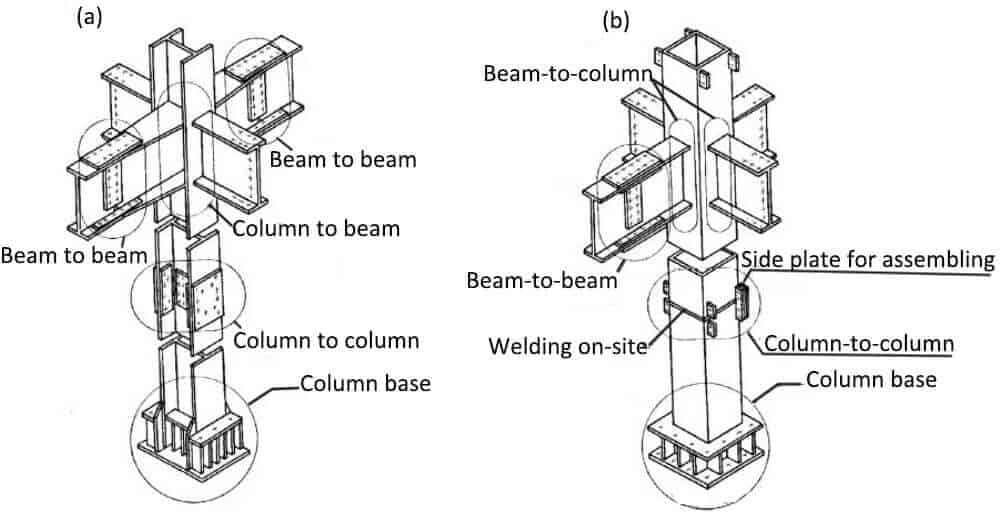
Connection detail
Steel Structure Detail for Truss Structure
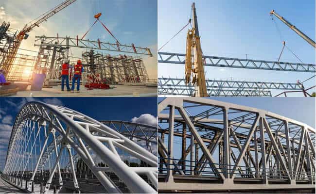
Steel Truss Structure
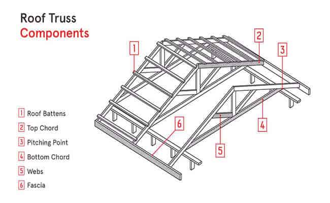
1. Angle Steel Truss
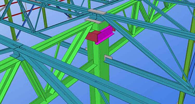
angle steel truss
2. Steel pipe truss:
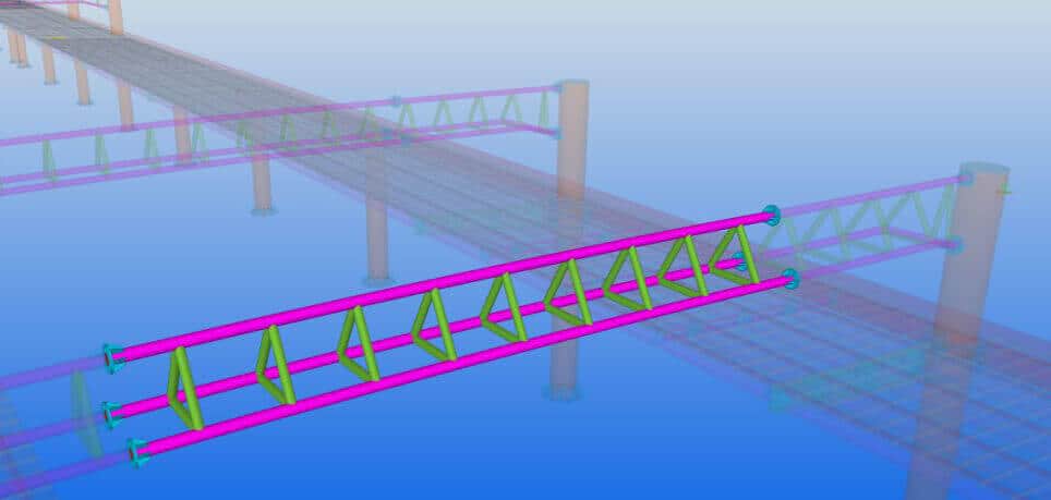
steel pipe truss
3. H-shaped steel truss:
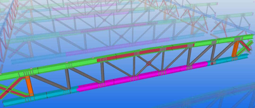
H shape steel truss
4. Box-shape steel truss:
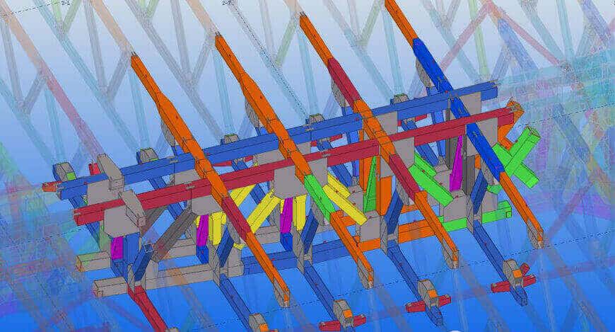
box-shape steel truss
Steel Structure Design
Steel structure design should include the following contents:
- Structural scheme design, including structure selection and component arrangement;
- Material selection and cross-section selection;
- Analysis of functions and effects;
- Check the limit state of the structure;
- Construction of structures, components, and connections;
- Requirements for production, transportation, installation, anti-corrosion, and fire protection;
- Unique performance design for structures that meet special requirements.
Steel structure design standards in different countries:
Canada: Canada’s steel structure design standards and specifications are formulated and issued by the Canadian Standards Association (CSA), including S16-14 and S16S1-19.
Europe: European steel structure design standards and specifications are formulated and issued by the European Committee for Standardization (CEN), including EN 1993-1-1, EN 1993-1-5, EN 1993-1-8, EN 1993-1-10, EN 1993-1-11, EN 1993-1-12, EN 1993-1-13, EN 1993-1-14, EN 1993-1-15 and EN 1993-1-16, etc. standard.
Japan: Japan’s steel structure design standards and specifications are jointly formulated and issued by the Japanese Society of Civil Engineers (JSCE) and the Japan Iron and Steel Federation (JISF). These include JIS G3101, JIS Multiple standards such as G3192, JIS G3193, JIS G3444, JIS G3466, JIS G3468, and JIS A5525.
China: China’s steel structure design standards and codes are formulated and published by the National Standardization Management Committee, including GB 50017, GB 50018, GB 50009, and GB 50011.
Basic principles of steel structure design
Steel structure design requires reasonable component selection based on the project’s needs and load requirements.
Load calculation is an indispensable part of steel structure design.
Connection design is also a crucial part of steel structure design.
Features of steel structure:
1. Save steel consumption and save investment
2. Prevent leakage; the effect is ideal
3. No piling required, shortening the construction period
4. Fast delivery and easy installation
5. The appearance is beautiful, and the interior is empty
- Pre:None
- Next:Pre Engineered Steel Structure 2024/4/16
