REEFER PASSAGES FOR SAFETY TUNNELS

(Reefer Tunnels and Reefer Passages between stacks and reefer racks)
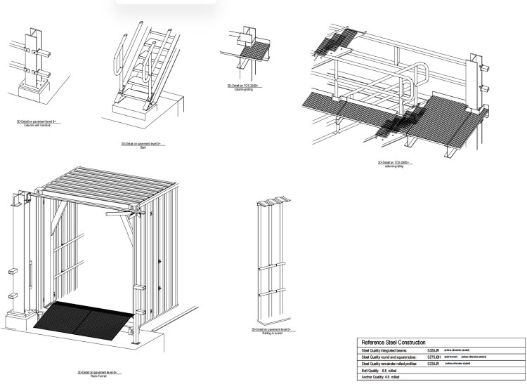
1.1. As detailed in section, reefer passages, shall be positioned as shown on the Definition and Information Drawings to provide a safe corridor for personnel to move between two racks, and to access the racks from the end of the stack. The passage will be made from modified 40’ and 20’ shipping containers.
1.2. The passage shall be modified from new 40’ container with dimensions of 12192mm (length), 2438mm (width) and 2896mm (height) and the access of the reefer passage shall be modified from 2 new 20’ container with dimensions of 6058mm (length), 2438mm (width) and 2896mm (height).
1.3. A buffer container filled with sand will always be placed on top of the reefer passage. Reefers are positioned on top of the passage (above buffer container).
1.4. The concept for the passage is shown on the Definition Drawing.

(Reefer Tunnels and Reefer Passages between stacks and reefer racks 3D Isometric View)

(Reefer Tunnels and Reefer Passages between stacks and reefer racks )
Part 2: Modifications
2.1 The following modifications to the container are required: Inspection Point
(a) The end walls and doors shall be removed and left as a clear opening.
(b) For the access the entire side wall of both 20”containers shall be removed and left as a clear opening.
2.2. A minimum of two window grills with size of 1000mm x 1000mm shall be set on the outside wall (i.e. towards the road/ARMG track/crane rail, away from adjacent containers) for air ventilation and lighting. The position of the grills shall not weaken the main frame of the container.
2.3. The floor of the container shall be concrete with sufficient roughness/anti-slip. The grating between the containers shall be flush with the concrete floor and drainage details shall be provided to prevent water ponding inside the passages.
(a) The passage shall contain fixed lighting and emergency lighting, as specified in Part I “Reefer Racks”.
(b) The load requirements detailed in Appendix I “Design Criteria” shall be considered in the modifications by the Contractor, in particular noting that the end walls have been removed and the side walls at passage entrance so some reinforcement will be required to ensure the rigidity and strength of the frame for the full design life.
(c) All additional bracing shall be inside the container (i.e. nothing fixed to the outside) so that there is no interference with container operations adjacent to or on top of the reefer passage. Any additional bracing or structural reinforcement shall not significantly reduce the clear opening or introduce trip hazards.

3.1. In order to minimise maintenance and adjustment of the passages, the container shall be securely fixed by twistlocks embedded into the ground, or by other effective means.Inspection Point If the foundations are to be constructed by a different contractor to the supplier of the passages, then the detailed requirements for the ground foundations shall be clearly provided to the Employer.
3.2. The passages shall be located relative to the reefer racks to match the container stacking alignment, both longitudinally and transversely. Inspection Point
3.3 The gap between the passage roof and the reefer rack, and between any two sections of passage, shall be closed at ceiling level to protect against small falling objects. The fixity of this roof section shall not interfere with placement of containers on top of the passage. Inspection Point
3.4. The steel floor grating shall be continuous between consecutive sections of passage without any change in level. Inspection Point
(a) If the top of the reefer rack foundation is at the same level as the passage floor, then any gap shall be covered with a steel grating to match the passage floor.
(b) Alternatively a step may be provided. Step should be in accordence with local regulation and sufficeint wide to place the whole foot safely. Subsequent steps up and down should be avoided. Any step down or up shall be clearly visible marked.
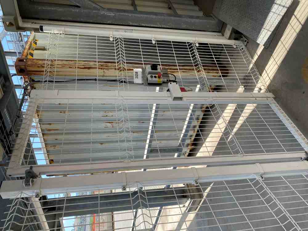
3.5. The vertical gap between the passage and the reefer rack, and between any two sections of passage, shall be closed with a mesh or chain-link fence at least 2 m high. Access gates and emergency exit gates shall be provided as specified in section 06D.4.3. Inspection Point
3.6 At either end of each row of passages, a ramp formed of steel grating shall be provided across the full width of the passage. A steel corner profile or chamfer of in-situ concrete shall be provided at the end of the steel grating ramp to tie it in with the ground level, without any step or trip hazard. Inspection Point
3.7. The passage colour shall be painted in a colour to be advised by the Employer. The paint and application method for passage can follow the container supplier’s standard materials and methodology. Inspection Point
06D.7.3.8 The lessons learned with regards to the reefer racks and reefer passage shall be taken into account in the design. Refer to ‘Other documentation’ for lessons learned of the reefer racks and reefer passage.

(Reefer Tunnels and Reefer Passages between stacks and reefer racks )
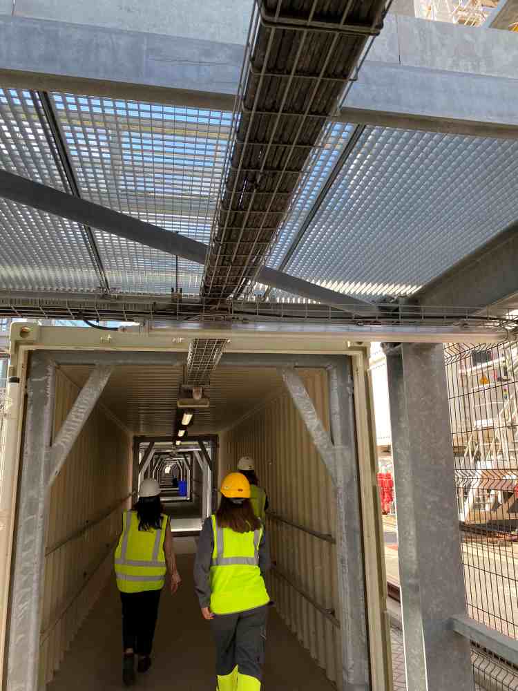
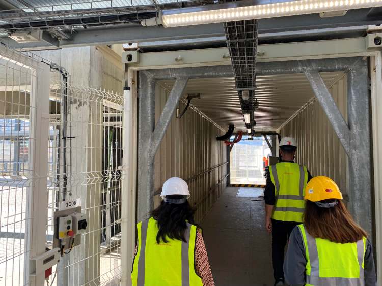
(Reefer Tunnels and Reefer Passages between stacks and reefer racks: Passengers safely walking through between stacks )
(Reefer Tunnels and Reefer Passages between stacks and reefer racks: Passengers safely walking through between stacks and wiremesh protection for external environment)
(Reefer Tunnels and Reefer Passages between stacks and reefer racks: Passengers safely walking through between stacks and wiremesh protection for external environment)
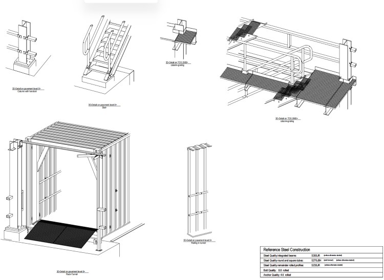
(Reefer Tunnels and Reefer Passages between stacks and reefer racks: As bult drawings for brand new container modification and reinforcement on pavement level 0.000)
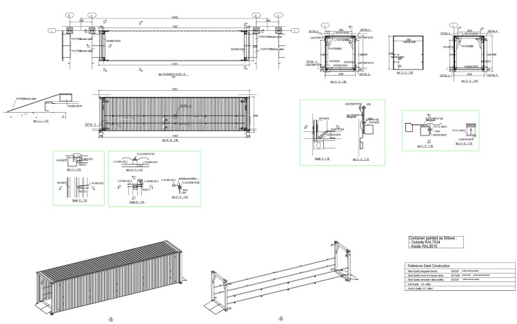
(Reefer Tunnels and Reefer Passages between stacks and reefer racks: As bult drawings for brand new container modification and reinforcement)
Would you like to see more information and images of ZHM’s Metal Steel Structure Safety Passage Tunnels for Reefer Rack ? Visit our Photo Gallery.
HOW CAN WE HELP YOU?
ZHM’s world-class team — together with our raw material suppliers and subcontractors — works to solve your most challenging design, engineering, farbrication or construction issues.
Contact ZHM by telephone at +86 135-8815-1981 or send us your questions via email to info@zhmsteelworks.com
- Pre:None
- Next:Metal Building Gymnasium Prefa 2024/5/22