Expansion Joint Considerations for Steel Buildings
Guidelines for dealing with dimensional changes in building structures due to changing temperatures.

All buildings are subjected to expansion and contraction due to the thermal loads from exposure to changes in the ambient temperature, both during construction and in operation. Local weather patterns along with the heating and air conditioning of climate controlled spaces will dictate the temperatures to which the structure is subjected. While these changes in temperature often take place slowly, the effects are the same. Warmer materials expand and colder materials contract. Depending on the anticipated temperature variation and materials used, expansion joints should be used in all buildings exceeding the lengths in Figure 1.
Why Expansion Joints Are Needed
The key to successful building design is recognizing that while the individual members in a structure may only experience small changes in length, the cumulative effects of these changes can become significant and should always be considered. This is especially important when looking at buildings with a large horizontal dimension. Expansion joints that separate the entire structure and roofing membrane will allow for the release of internal stresses that would otherwise build up. This will help to ensure that relatively brittle cladding, particularly masonry, is not subjected to excessive displacements and consequential separation or cracking,
which could allow water to penetrate into interior spaces.
Federal Construction Council Technical Report No.65, Expansion Joints in Buildings, published by the National Research Council (NRC) in 1974, is an excellent reference on thermal expansion in buildings, determining when potential thermal movement must be addressed, and the design of expansion joints where required. The report recommends a maximum allowable building length without the use of an expansion joint in terms of design temperature change and building material. Figure 1 was developed considering beam and column construction, hinged column bases, and heated
interiors. If actual conditions differ from those assumed conditions, a percentage factor is applied to the results obtained in the figure following these guidelines:
1. If the building will be heated only and will have hinged column bases, use the allowable length as specified.
2. If the building will be air-conditioned as well as heated, increase the allowable length by 15% (provided the environmental control system will run continuously).
3. If the building will be unheated, decrease the allowable length by 33%.
4. If the building will have fixed column bases, decrease the allowable length by 13%.
5. If the building will have substantially greater stiffness against lateral displacement at one end of the plandimension, decrease the allowable length by 25%.
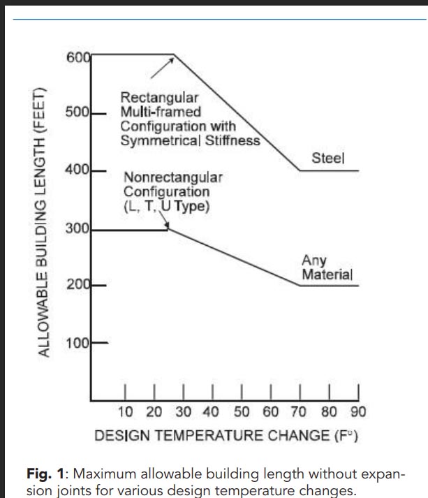
Fig. 1: Maximum allowable building length without expansion joints for various design temperature changes.
When more than one of these design considerations prevails in a building, the percentage factor to be applied should be the algebraic sum of the adjustment factors of all applicable conditions.
Buildings with a large horizontal dimension will require expansion joints. There are no exact requirements that state when expansion joints should be used, but the best practices use Figure 1 as the guide on the maximum allowable spacing between joints. Because there is a cost associated with each expansion joint, the general preference is to use fewer joints with a larger spacing between joints rather than more joints
with a smaller spacing.
Expansion Joints in Buildings lays out a thorough procedure on how to determine the design temperature change. Unless more specific site information is available, most engineers assume a range of 50° to 70° F for continuously heated and air-conditioned buildings. Using that assumption, most steel, rectangular, framed configuration buildings with symmetrical stiffness can tolerate 600 ft between expansion
joints. This may be reduced based on thermal exposure data and irregular geometric configurations.
Where to Locate Expansion Joints
Several locations should be considered when placing an expansion joint. Locations where differential movement is likely are prime locations, such as at the connection between a building addition and the original construction, or where different materials come together. For example, if steel decking and precast plank abut each other, this is an excellent location for placing expansion joints. Other preferred locations are areas that feature a change or a turn in geometry, such as in the reentrant corner of an L-, U- or T-shaped building or at a setback or bump out in the exterior envelope.
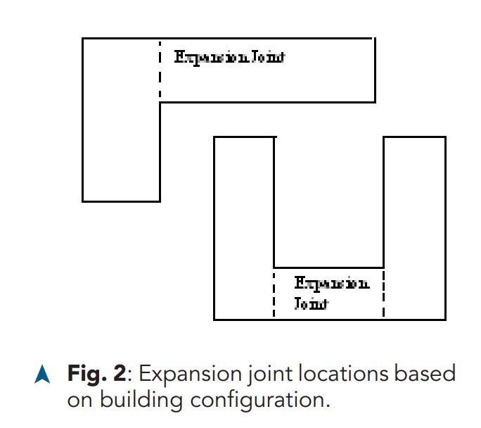
Fig. 2: Expansion joint locations based on building configuration.
Types of Expansion Joints
The best way to account for the effects of thermal expansion and contraction is by incorporating a double line of columns into the structure where the stress release is intended, essentially creating two separate buildings adjacent to each other. While this is the most desirable solution, and one of the best performing options, it is also one of the more expensive options.

Fig. 3: Typical components for a slip surface joint at a bearing connection.
The slip surface joint at a bearing connection is the next best alternate, and the most common way to allow the differential movement. Note that the use of shear connections with long slotted holes is not recommended. The bolts tend to saw into the sides of the holes, locking the joint. Also, long slots allow only limited movement (half the slot width at best; less if the bolt is not centered when erected) and thermal elongation and contraction usually require more movement capacity. When a bearing pad detail is used, the key to success is the frictionless bearing surface. The knife plate connections are typically requiring the load to be transferred through the bolts, which are already loaded in shear, and if there is any binding of the bolts on the plate—due to spurs, dirt or inclusion of the bolt threads—a cutting action will start to develop instead of a sliding action. Ultimately, that can lead to loss of section and potential failure. For these reasons, the bearing style connection and the double column are the preferred methods for stress release due to thermal loading.
Code Requirements and Commentary Recommendations
The AISC Specification for Structural Steel Buildings (ANSI/AISC 360-10) addresses the topic of expansion and contraction in Chapter L - Design for Serviceability. Section L7 states:
“The effects of thermal expansion and contraction of a building shall be considered. Damage to building cladding can cause water penetration and may lead to corrosion.”
ASCE 7-10 Minimum Design Loads for Buildings and Other Structures covers the topic of expansion and contraction in Appendix C—Serviceability Considerations. Section C.4 states:
“Dimensional changes in a structure and its elements due to variations in temperature, relative humidity, or other effects shall not impair the serviceability of the structure.“Provisions shall be made either to control crack widths or limit cracking by providing relief joints.”
The commentary goes on to discuss the following, which is a summary (See the commentaries to the AISC Specification and ASCE 7 for further information):
There are too many variables when looking at issues of expansion and contraction to create a simple set of rules that govern design. This is ultimately a serviceability issue that must be left to the judgment of a qualified engineer. If the components that are subjected to the movements of thermal expansion are highly sensitive to
differential displacements, the tolerances will be much lower when considering maximum elongation values. This may require the designer to place expansion joints at a closer spacing than would be provided for a similar building with less stringent movement requirements. Additionally, there may be other factors like creep, shrinkage, yielding, or swelling of members that contribute to the displacements which are allowed for
in the design of expansion joints. The governing design condition may occur during construction and be less severe when the structure is enclosed and in operation.
One guideline to consider when designing for expansion is to allow the structure to move as a whole as much as possible and to keep the differential movement of components to a minimum. It is also important to ensure that the design allows for sufficient load reversal to account for the effects of contraction as well as expansion of components. There may be components of the expansion or contraction that are the result of permanent deformations. It is necessary to account for this type of behavior because it may require that the allowable slip in a joint be greater in one direction that the opposite direction.
In the end, the internal stresses generated by thermal loads or other sources will find a mechanism for release. If there is not a well thought out path or design component to control this stress release, an unintended crack will develop somewhere in the structure. If that is the intended mechanism for the release of internal stresses, then designers are advised to provide a mechanism to control the widths of the cracks that will develop. Without providing expansion joints or controlling crack widths, the structure will likely suffer the effects of water infiltration and the secondary effects of corrosion and other adverse conditions.
Additional Information
➤ More information about expansion joints can be found in the NRC document Expansion Joints in Buildings. The document is available as a free downloadable PDF
➤ There is a steelTOOL available at www.steeltools.org called THERMAL, posted by Alex Tomanovich. This design aid helps with calculating the maximum allowable building length between expansion joints, the change of length due to thermal effects, and the appropriate maximum design temperature change.
➤ AISC Steel Design Guide No. 7, Industrial Buildings–Roofs to Anchor Rods, includes a small segment on expansion joints. Design Guide 7 is available as a free download for AISC members, and for a fee for non-members, at www.aisc.org/dg.
➤ The 2005 NASCC featured a presentation called “Expansion Joints: Where, When and How,” by James Fisher. The full paper is available as a free download for AISC members through the AISC website, www.aisc.org, and can be found by searching for “expansion joints proceedings.”
- Pre:None
- Next:Expansion Joint Considerations 2024/4/26