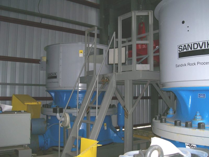
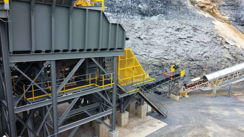
Secondary Tertiary Crushing Station Buildings Featuring Four (4) Crushers
_crushers.jpg)
Secondary Tertiary Crus
Secondary Tertiary Crushing Station Buildings Featuring Four (4) Crushers
_crushers.jpg)
Secondary Tertiary Crushing Station Buildings Featuring Four (4) Crushers
Introduction:
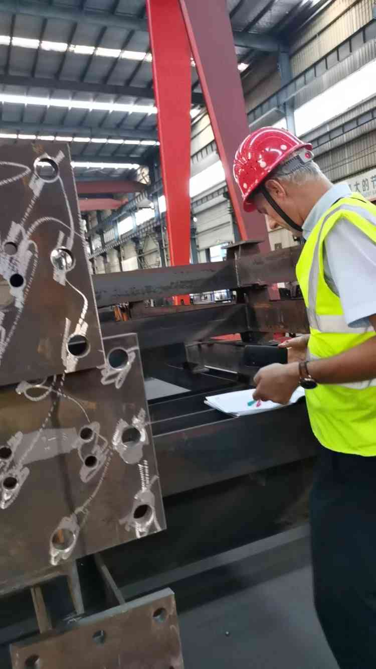
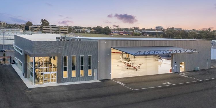
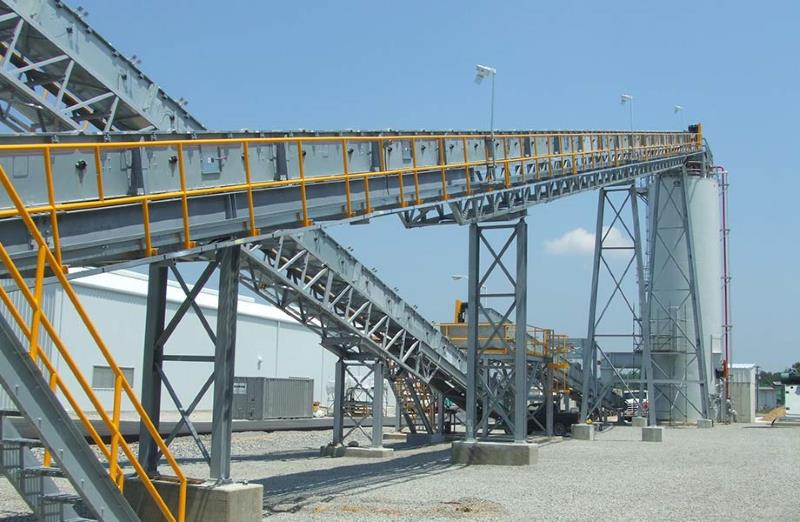
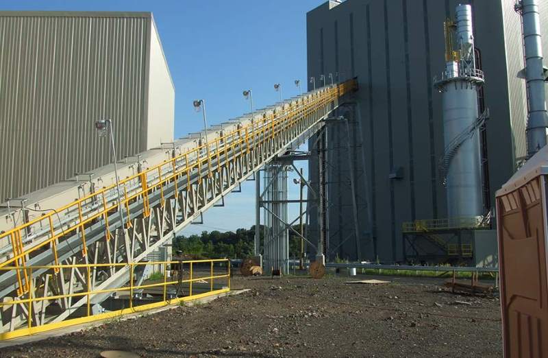
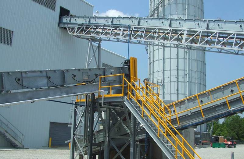
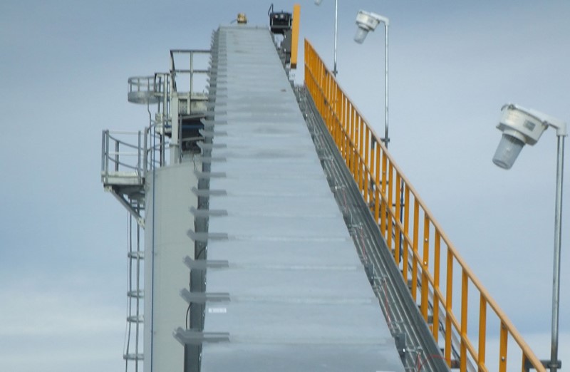
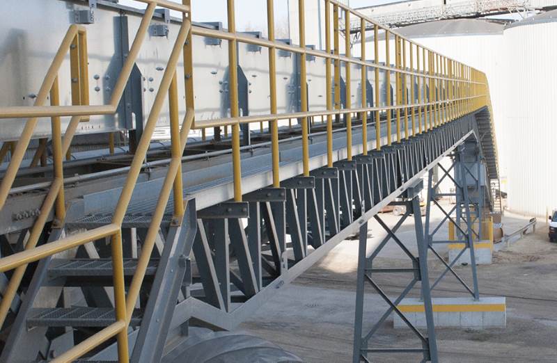
ZHM Huawu Steel design and manufacture heavy duty hoppers, feeders & frame conveyors for all industrial and commercial applications,These designs performs in tough environments while protecting the product from the weather conditions, capturing of dust emissions, while limiting the risk of igniting flammable products. Common options include: trussed frames, walkways, service platforms, support bents, transfer towers, and reloading tail sections.
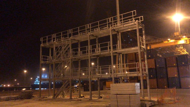
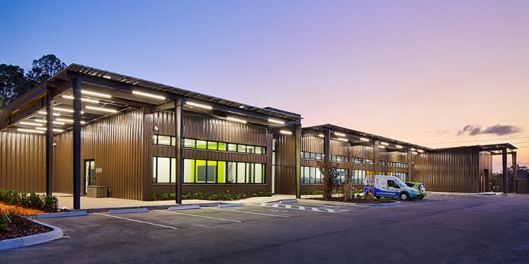
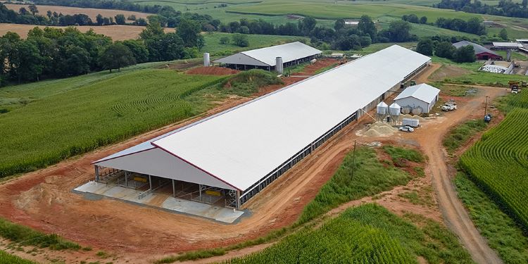
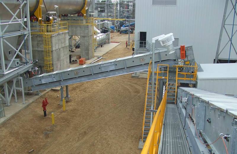
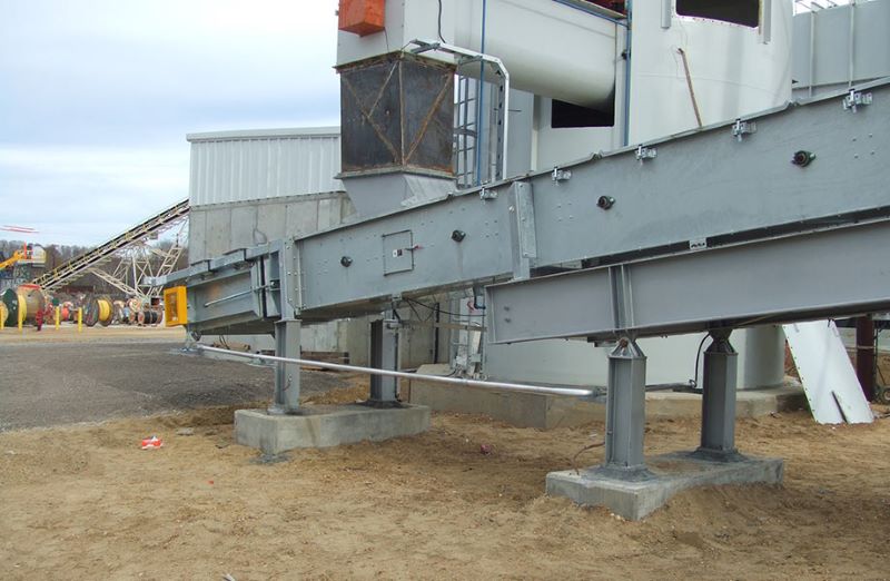
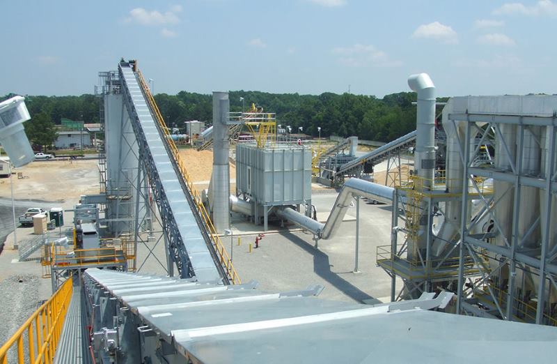
Crushing stations are just one of the many elements that make up a processing plant. No matter what the capacity or the material your plant is processing, ZHM Huawu Steel can help design, fabricate and install a crushing station that will serve the purpose well. We have experience in designing for all stages of crushing which also includes the satellite elements such as hydraulic breakers, retaining walls, operators control buildings and the structural steel associated with each element. All of our crushing stations can be fully enclosed to satisfy any dust or noise control requirements a producer may encounter.
The scope of structural steel works:
The scope of structural steel works for Crusher Station Buildings, Feed&Discharge Conveyor Steel Structures usually included the followings:
1. Structural Steel (All Type & Size Members) Raw Material Supply, Fabrication and Site installation of all type & member sizes Structural Steels as sandblasted and painted, Gratings, stair treads, fasteners (Bolts, Nuts, Washers) as per details and design made by ZHM Huawu Steel;2. Sandblasting & Painting
3. Grating (30*3mm)
4. Stair Treads (L750)
5. Fasteners (Bolts, Nuts, Washers)
6.the supply, fabrication and erection of Building and Conveyor Steel Structures and Plate/Chute Works, associated assemblies and site erection
Project Showcase:
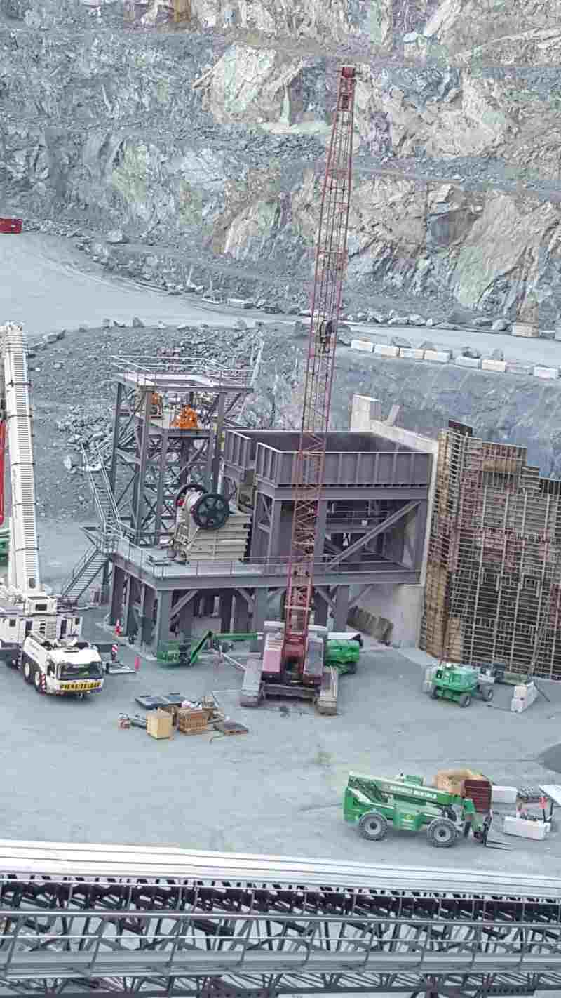
The Asanko Gold Mine (AGM) is Galiano’s flagship asset since 2016, located in Ghana, West Africa. It is full owned and operated by Galiano, with a 10% interest held by the Government of Ghana.
The AGM is a multi-deposit complex, with four main open-pit mining areas: Abore, Miradani North, Nkran and Esaase, and multiple satellite deposits, situated on the Asankrangwa Gold Belt, and a 5Mtpa carbon-in-leach (CIL) processing plant. Gold production commenced in January 2016 and commercial production was declared on April 1, 2016. Galiano Gold is focused on creating a sustainable business capable of value creation for all stakeholders through production, exploration and disciplined deployment of its financial resources. The Company operates and manages the AGM, located in Ghana, West Africa, jointly owned with Gold Fields Ltd. Galiano is committed to the highest standards of environmental management, social responsibility, and the health and safety of its employees and neighboring communities.
The common, standardized basis for steel works and materials supplied and erected for the entire construction of the permanent project. The stated purpose of this article is to clearly demonstrate that the work performed will result in a safe and fully operable structural system in accordance with the regulations, specifications, contract documents and drawings.
ZHM Huawu Steel design and manufacture heavy duty hoppers, Feed&Discharge Conveyor Steel Structures
Primary crusher station buildings with rock box hopper and hydraulic breaker support structure, Feed&Discharge Conveyor Steel Structures
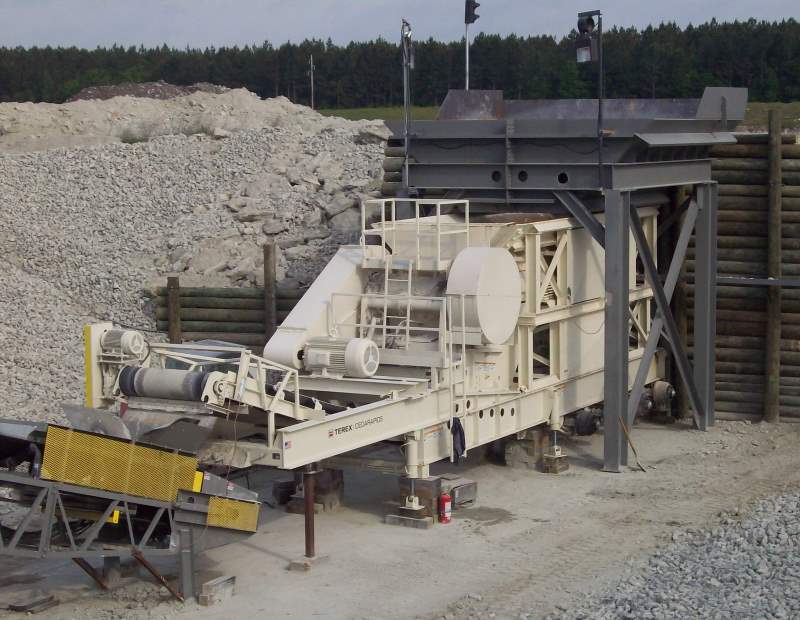
Semi-portable Secondary Crushing Station Building, Feed&Discharge Conveyor Steel Structures
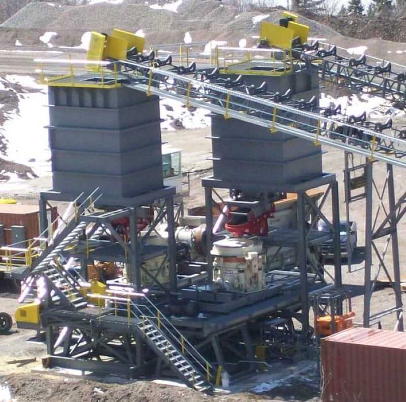
Dual secondary crushing station building with dedicated surge bins/feeders, Feed&Discharge Conveyor Steel Structures
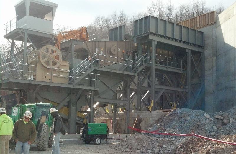
Primary crushing station building with scalper screen prior to jaw crusher, Feed&Discharge Conveyor Steel Structures
Primary crusher station with Rock box primary dump hopper with jaw crusher, Feed&Discharge Conveyor Steel Structures
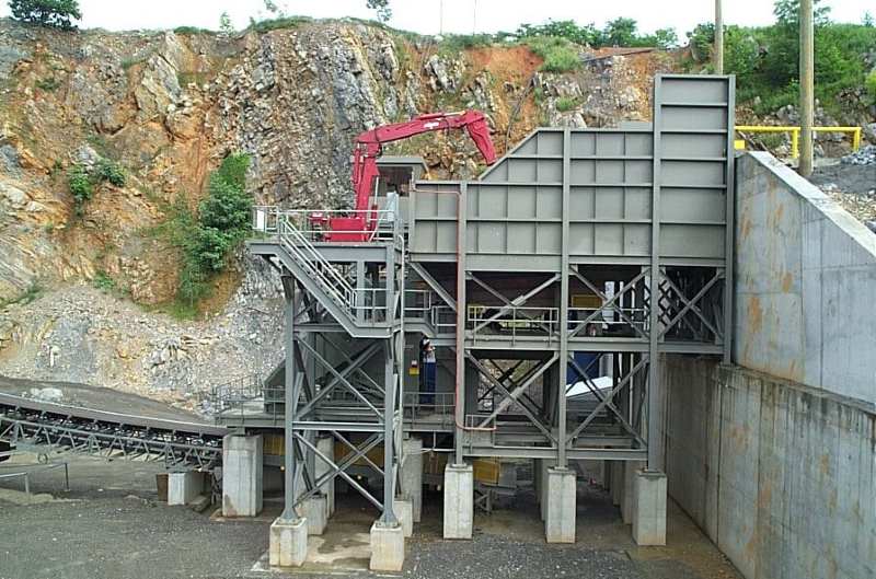
Primary crushing station with hydraulic breaker and control tower, Feed&Discharge Conveyor Steel Structures
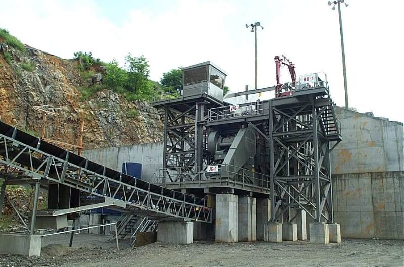
Primary crushing station with hydraulic breaker and control tower, Feed&Discharge Conveyor Steel Structures
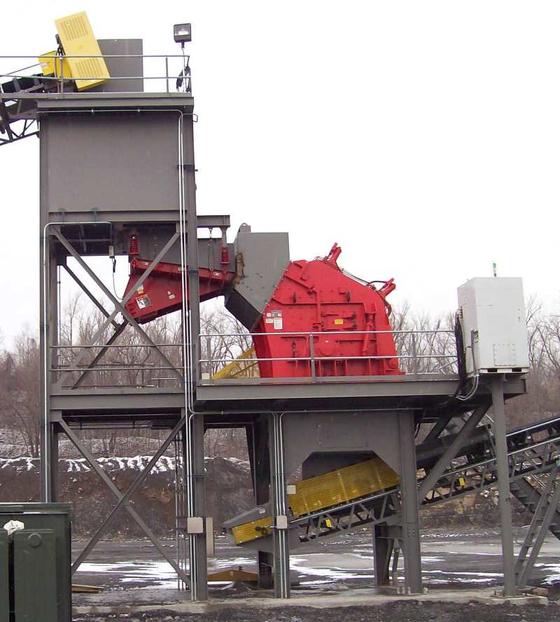
Tertiary crushing station featuring a horizontal shaft impact crusher with a surge bin and feeder, Feed&Discharge Conveyor Steel Structures
Crushing station featuring a horizontal shaft impact crusher in a recycled asphalt application, Feed&Discharge Conveyor Steel Structures
Primary jaw crusher station with rock ox hopper, Feed&Discharge Conveyor Steel Structures
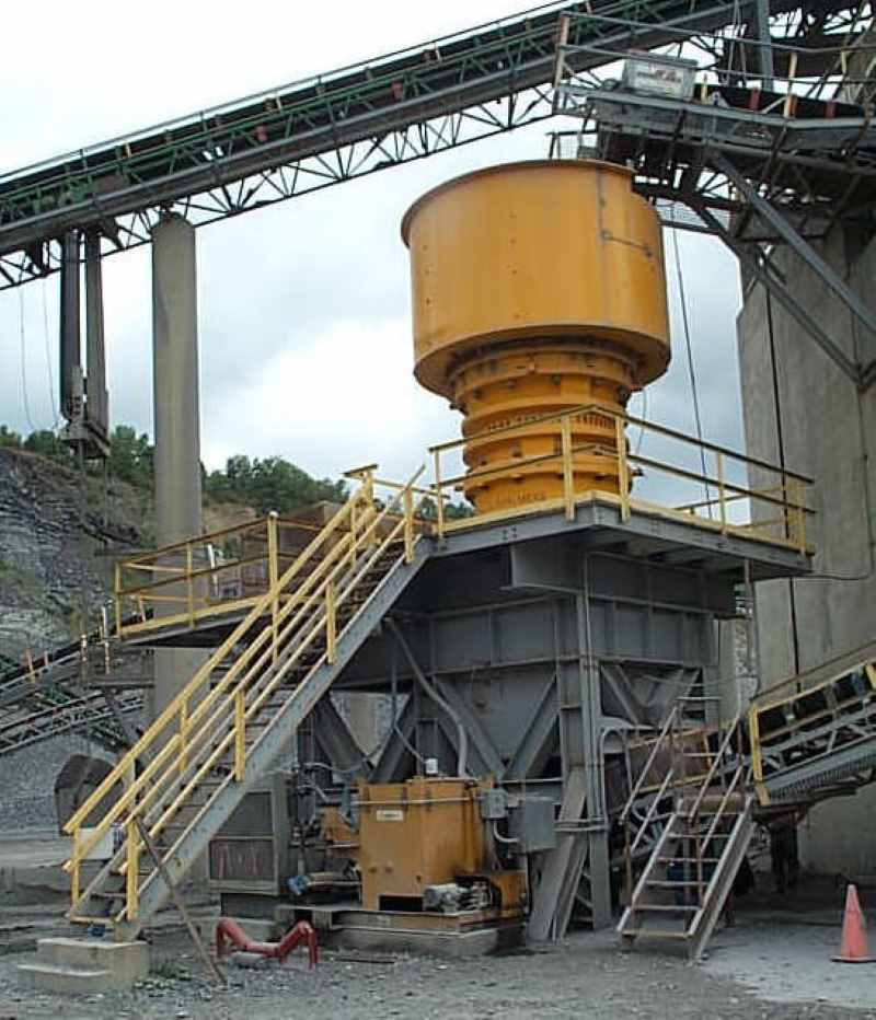
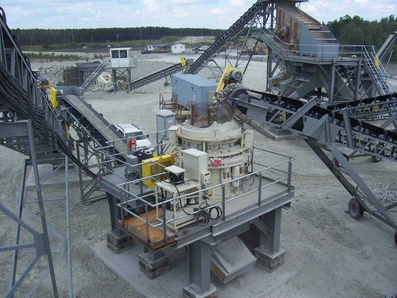
Secondary cone crusher station, Feed&Discharge Conveyor Steel Structures
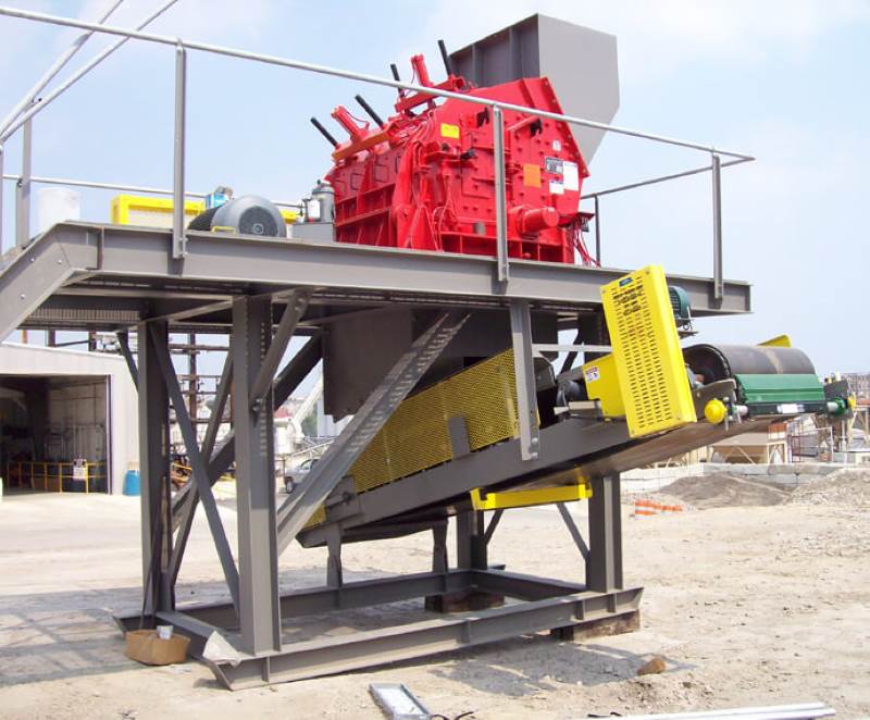
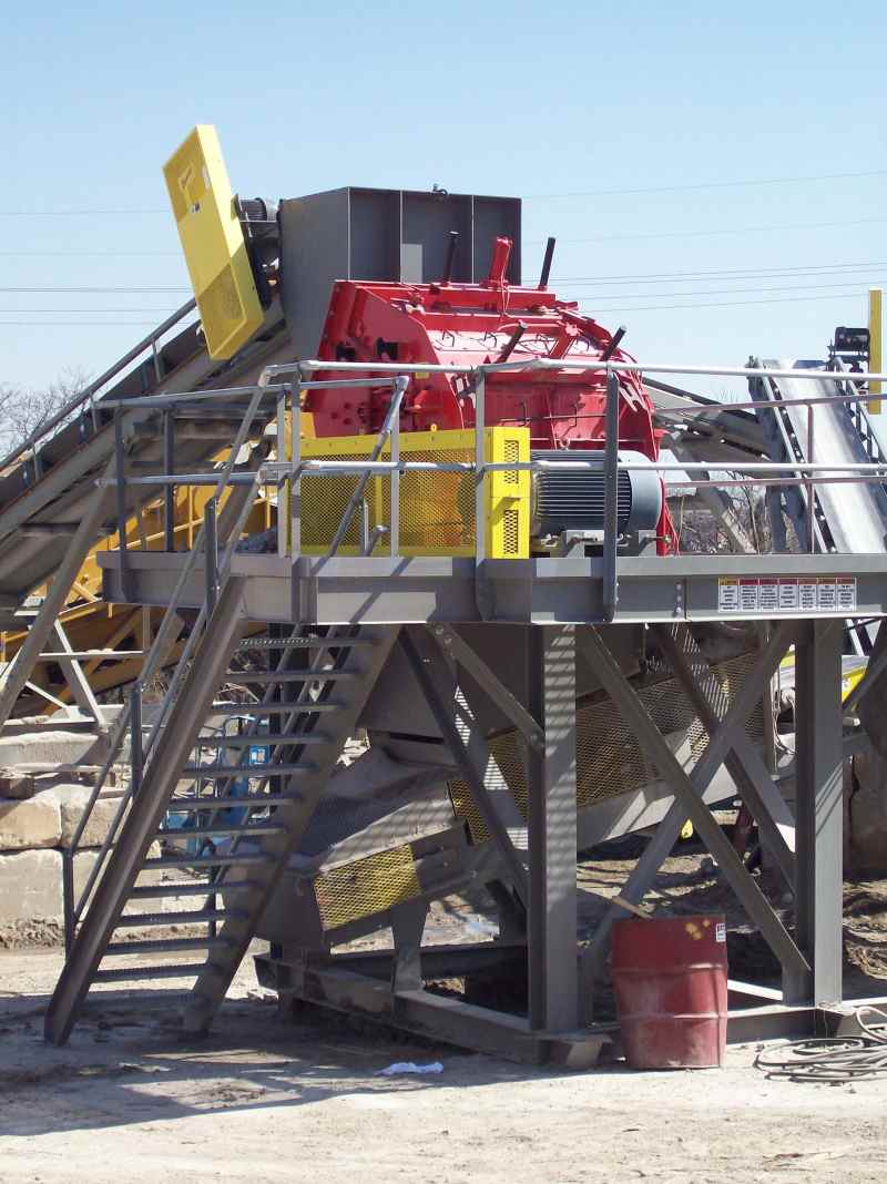
Crushing station featuring a horizontal shaft impact crusher with side discharge conveyor; semi-portable, Feed&Discharge Conveyor Steel Structures
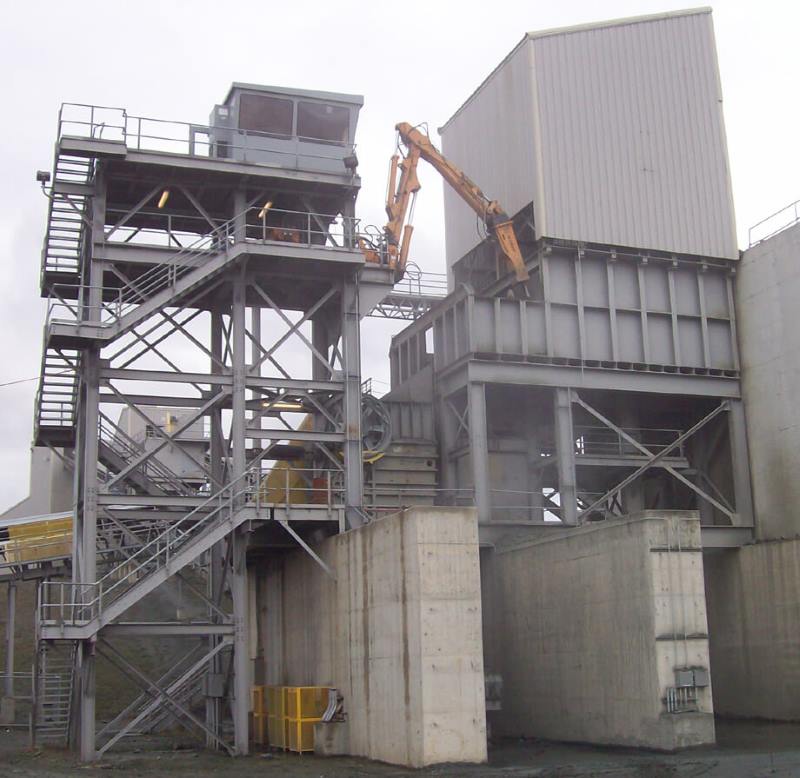
Primary crushing station with enclosed rock box hopper, hydraulic breaker and operators booth, Feed&Discharge Conveyor Steel Structures
Primary crushing station utilizing a portable jaw plant, Feed&Discharge Conveyor Steel Structures
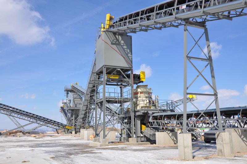
Secondary cone crushing station with surge bin and belt feeder, Feed&Discharge Conveyor Steel Structures
_crushers.jpg)
Secondary/Tertiary crushing station featuring three (3) crushers, Feed&Discharge Conveyor Steel Structures
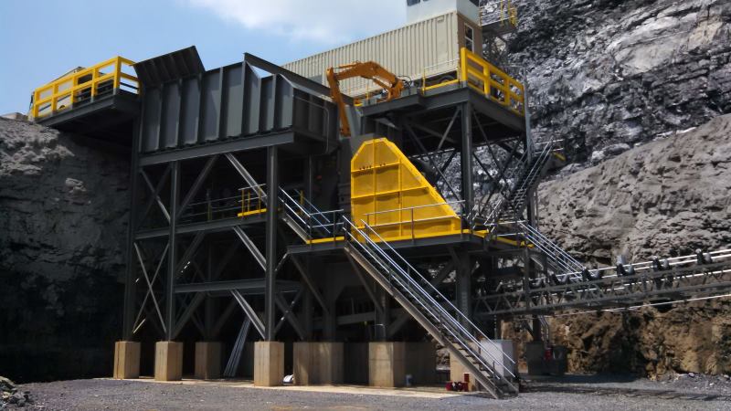
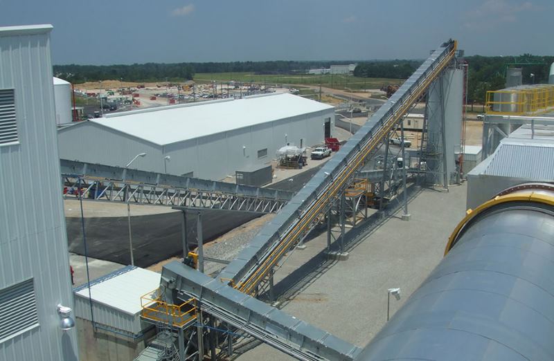
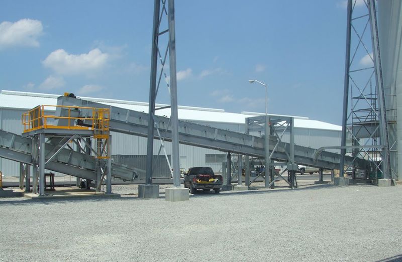
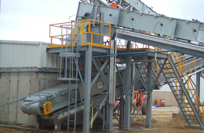
Secondary/Tertiary crushing station featuring four (4) crushers, Feed&Discharge Conveyor Steel Structures
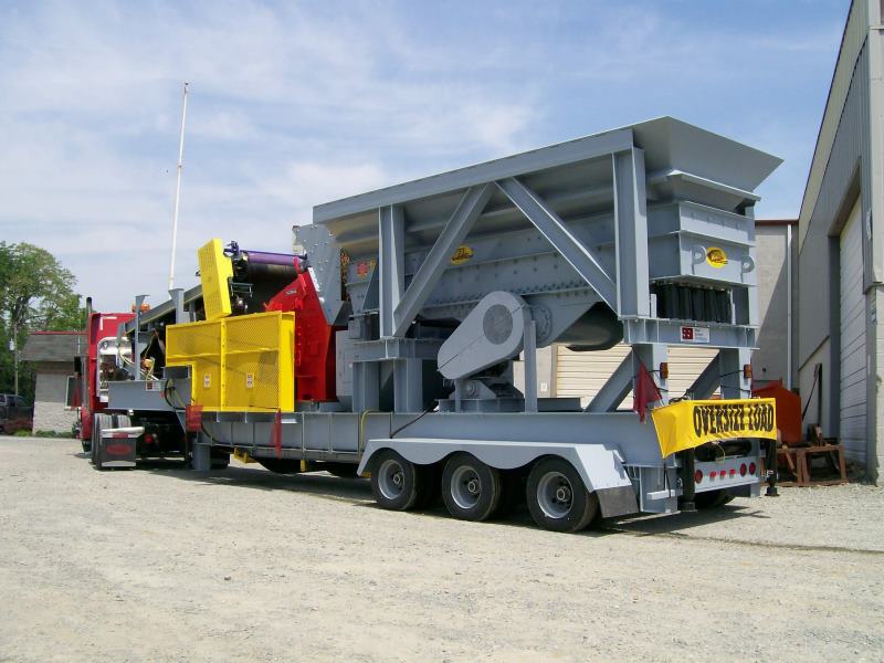
Portable crushing plant featuring a horizontal shaft impact crusher, Feed&Discharge Conveyor Steel Structures
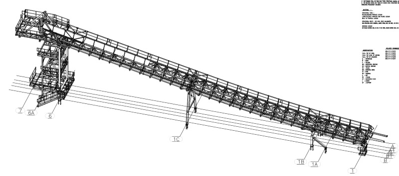
Primary station with rock box hopper and hydraulic breaker support structure, Feed&Discharge Conveyor Steel Structures:3D Model for Crusher Station Buildings

Crusher Station Buildings, Feed&Discharge Conveyor Steel Structures-Plan View
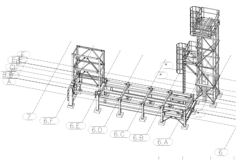
Crusher Station Buildings, Feed&Discharge Conveyor Steel Structures:Chasis 3D View
1 Materials
1.1 Construction Materials
1.1.1. Structural Steel
.1 Hot-rolled sections (except angles) - 355MPa (S355JR)
.2 Hot-rolled equal leg angles up to and including 50mm leg length - 200MPa (CQ Material)
Minimum.
.3 Al other hot-rolled equal leg angles and al unequal leg angles - 355MPa (S355JR)
.4 Structural hollow sections - 300MPa (300WA) Minimum
.5 All platework - 275MPa (S275UR) Minimum
.6 Cold-formed lipped channels - 200MPa (CQ Material) Minimum
.8 Unless otherwise specified in the material specification or in the inspection- and testing plan,the inspection (material test) certificates specified in below Table will be followed for the steels to be processed.
|
Steel Grade |
Material Test Certificate |
|
S235JR |
EN10204 Type 2.2 |
|
S235J0, S235J2+M, S235J2+N, S355JR, S355J0,
S355J2+M, S355J2+N
|
EN10204 Type 3.1 |
1.1.2.Bolts, Nuts and Washers:
.1 All bolts, nuts and washers to be hot dip galvanised with tree turning nuts to relevant section of SANS 1700. In Cyanide and corrosive areas the Galvanised bolts shall be primed and painted as per the paint specification for corrosive areas.
.2 Al bolts, nuts and washers shall be minimum M20, Grade 8.0 with Grade 8 nuts, (U.O.N.) for all structural connections.
.3 Bolts, nuts and washers (under nuts) for mechanical plate-work and hand-railing shall be minimum M16, Hot dip galvanised, Grade 8.8 with Grade &nuts. (Stair treads - M12). Bolts to be spaced 150mm for wet platework and 200mm for dry conditions.
.4 Taper washers are to be used where required by the steel section.
.5 All liner plates to be fastened with countersunk nib head bolts with Nyloc nuts or equivalent.
2.Fabrication
2.1 Cutting
.1 Where the ends of members are to bear in compression, the ends shall be cold sawn and then machined so that the loads are evenly transmitted over the entire area of the section..2 In all other cases, setting may be by shearing, cropping or sawing. Notches or other shaping to the ends of members shall be formed by cold or hot sawing.
.3 Machine Flame cutting may be used only where approved, in writing by the Owner.
.4 Manual flame cutting shall not be allowed under any circumstances.
.5 Edges shall be free from any defects which would adversely affect the serviceability of the member. All burrs and similar defects shall be carefully removed. The edges of flame cut plates shall, unless otherwise agreed by the Consultant be machined to remove notches, the heat
affected zone or both.
.6 Flame/thermal cuts must be deburred regarding the burrs.
.7 For flame cutting the freedom from any corrosion by condensed water must be ensured.
.8 All sharp edges must comply with the corrosion protection requirements (chamfering, as required).
.9 Thermal Cutting: The capability of automated thermal cutting processes shall be checked annually as set out below. Four samples shall be produced from the constituent product to be cut by the process:
- a. a straight cut from the thickest constituent product.
- b. a straight cut from the thinnest constituent product.
- c. a sharp corner from a representative thickness.
- d. a curved arc from a representative thickness.
2.2 Holes For Fasteners
.2 All burrs shall be removed from holes before assembly except that, where holes are drilled in one operation through parts which would not otherwise be separated after drilling, the parts need not be separated to remove the burrs provided that the holes are for black bolts only.
.3 Finished holes for black bolts shall not be more than 2 mm in diameter larger than the diameter of the bolt passing through them for bolt diameters up to 24 mm and not more than 3 mm larger than the diameter of the bolt for diameters over 24 mm unless otherwise specified by the Owner or required by the design.
.4 Slots, where specified or permitted, shall be formed using a proper slotting machine. Alliteratively, holes may be drilled and the metal between removed by filling or other approved method provided that the surface between the circular ends is even and straight.
2.3 Welding Operations
.2 Stud shear connectors, where specified, shall be welded in accordance with the manufacturer's instructions.
.3 For any load-bearing structural parts, columns, crossbeams, diagonal stays, etc. an allocation of the welder to the seams welded by him is to be ensured. This can be achieved by a stamping of the seams with the relevant welder's number or allocating of the welder stamp by marking in a drawing/sketch.
a. For every welding procedure and filler metal (type designation according to the standard) for steels ≤ S355,
b. For every welding position which occurs in the production
c. Steels > S355 separated agreement.
d. Fillet welds shall be qualified separately and shall not be covered by butt welds.
4.2.2. Welder's Qualification Tests (WQT)
.5 Welders must have a valid welder's qualification certificate according to EN/ISO norms. In addition to EN/ISO norms it is defined that welders who perform the fillet welding must have welded a fillet weld test piece. Operators must have a valid operator's qualification record
according to EN/ISO.
a. The technical qualification must have been proved.
b. The scope of qualification must cover the welder’s/operator’s scope of app
4.2.3. Quality of Welds
.1 All slags, weld spatters, ignition points and deposits due to welding must be removed. Any auxiliary materials resistant to spatters are subject to the explicit approval by Owner.
.2 Any inadmissible notches must be removed in a professional manner – primarily by flush grinding, in particular cases by re-welding.
.3 Preheating and temperature of intermediate layers, rate of cooling and as required heat control and heat application depend on the specifications of each applicable welding procedure qualification test (WPQR/ WPAR).
.4 A sufficiently wide and homogeneous heat distribution (≥ 50 mm on both sides of the groove as a function of the component thickness and ambient temperature) is to be ensured.
.5 Welding points must be protected against harmful weather influences, e.g. precipitation, condensation water, draught and wind.
4.3. Testing of Welds
.1 Owner reserves the right to demand test welds. The weld seam quality is evaluated according to the criteria of standard EN ISO 5817 (see also below Table).
.2 The following testing shall be applicable to non-destructive tests:
- a. (VT) Visual inspection
- b. (PT) Dye penetrant inspection
- c. (MT) Magnetic particle test of welded joints
- d. (RT) Radiographic inspection
- e. (UT) Ultrasonic inspection
|
Weld Joint |
NDT Ratio |
NDT Ratio |
NDT Ratio |
|
Weld Joint |
VT
(%)
|
RT or UT
(%)
|
MT
(%)
|
|
Full Penetration Butt Welds
|
100 | 100 | 20 |
|
Fillet Welds
|
100 | --- | 20 |
|
T-Joint Butt Welds
|
100 | 100 | 20 |
4.4. Payment For Testing
.1 ZHM Huawu Steel, as the Manufacturer, will include in his rates for the cost of providing and using equipment for the non-destructive testing of welds (radiographic, ultrasonic, dye penetrate and
magnetic particle), during fabrication and on site as required by the radiographic films and other test results and reports available to the Owner.
.1 Steel plate work shall be protected against corrosion by the application of coatings as shown on the drawings and specified below. The EU/ISO standards and guidelines shall be binding for the corrosion protection, unless otherwise specified by Owner.
4.5.1. Surface Preparation
.1 The surface preparation of any non-galvanized parts shall be done by means of dry abrasive blast cleaning.
.2 In this respect, all steel parts including the weld seams are de-rusted according to EN ISO12944-4 immediately prior to the application of the primer coat by means of dry abrasive blast cleaning at least until the standard preparation grade Sa 2½ is reached. For any cast parts of metal an
equivalent pre-treatment is taken for granted.
.3 For any non-galvanized parts any rust, welding residues, weld spatters, slag, burrs, salt, atypical impurities and similar must be removed from the surfaces prior to blast-cleaning. Rust, weld spatters, slag, burrs must be removed. Any boreholes shall be considered as surfaces and
accordingly prepared in an equivalent manner. Any existing edges from flame cuts, saw cuts, punched holes and cutting work, etc. shall be chamfered. Any screw holes and boreholes shall be deburred.
4.5.2. Application of Painting
.1 The application of the factory-made coating(s) shall be affected in closed rooms by airless guns. All corners, clearances, screw holes and hardly accessible areas must be pre-painted after the surface preparation. The primer coat shall be applied immediately after blasting. For the application of the intermediate and finishing coats the rework periods shall be complied with according to the manufacturer's specifications.
.2 The specifications of the paint supplier must be followed with priority.
.3 For the storage and processing of the coating materials the regulations of the coating manufacturer shall be additionally observed.
.4 Before the start of any corrosion protection work the Contractor must inform the Owner as follows:
- a. execution site
- b. period of execution
- c. any commissioned subcontractors
- d. any applicable coating materials and coating systems incl. manufacturer ZHM Huawu Steel
.5 Inspections of the corrosion protection work shall be made possible to the Owner, the coating manufacturers and any companies commissioned with the application of the later finishing coats at any time and without prior notice.
.6 The specified film thicknesses are to be understood as nominal dry film thicknesses according to EN ISO 12944-5. In this respect, any individual values of the dry film thickness, which are below 80 % of the nominal dry film thickness, shall not be permissible. Individual values between 80 % and 100 % of the nominal dry film thickness are permissible, provided the mean value of all measuring results is equal to or greater than the nominal dry film thickness.
.7 For the max. film thickness the data in the Technical Data Sheet of the coating supplier shall be applicable. If no data is contained in these data sheets, the max. film thickness must not be greater than three times the nominal dry film thickness.
.8 For any applied factory-made coating systems with multiple layers the coating materials shall be purchased from the same manufacturer.
.9 In case of any contact surfaces of pre-stressed screwed connections the contact plate surface may only be provided with a prime coat. A thickness of max. 60 μm is sufficient.
.10 All used fasteners, also galvanized screws, shall receive an equivalent coating structure.
.11 Apart from components, which are delivered according to supplier standard, the following paint
suppliers are released:
- a. Akzo Nobel / International
- b. Sigma Coatings
- c. Hempel
- d. Sika Protective Coatings
- e. Jotun
4.5.3. Painting System
- The formulation of paint shall comply with SANS and EU norms.
- All paints forming anyone painting system shall be obtained from one manufacturer and the source of supply shall not be changed. Paint shall be supplied in sealed containers and shall be used in strict order of delivery.
4.5.3.1. COATING/PAINT SYSTEMS
4.5.3.1.1. System 1 (indoors)
Description:
This specification covers the coating of structural steel work, plate work, not insulated, system correspondence to C3 according to EN ISO 12944.
Examples for Application areas:
- Steel structure inside of buildings
- Stairs, platforms, brackets, girders
- Railings, vertical ladders
- Vertical members, corner connection
- Pipes, pipe supports
- Cold air ducts (inside and outside surface), Tanks
- Temporary support for erection of steel structure etc.
Surface preparation:
Blast-cleaning according to ISO 8501-1 grade Sa 2 ½. Surface roughness according to the specifications of the coat supplier.
|
|
SYSTEM 1
|
|
|
Layer
|
Paint Type
|
Nominal Dry Film Thickness
(NDFT)
|
|
Prime Coat
|
Two-component epoxy resin (EP) zinc phosphate primer.
Clearly other colour shade than top coat
|
100 μm
|
|
Top Coat
|
Two-component acrylic-polyurethane (PUR).
|
80 μm
|
|
|
Sum | 180μm |
4.5.3.1.2. System 2(outdoors)
Description:
This specification covers the coating of structural steel work, plate work, not insulated parts which directly subjected to weather effects, system correspondence to C5-I according to EN ISO 12944.
Examples for Application areas:
- - Steel structure outside of buildings
- - (outside) Stairs, platforms, brackets, girders
- - (outside) Railings, vertical ladders
- - (outside) Vertical members, corner connection
- - (outside) Pipes, pipe supports
- - (outside) Cold air ducts (inside and outside surface), Silos, Tanks etc.
Surface preparation:
Blast-cleaning according to ISO 8501-1 grade Sa 2 ½. Surface roughness according to the specifications of the paint supplier
|
|
SYSTEM 2
|
|
|
Layer
|
Paint Type
|
Nominal Dry Film Thickness
(NDFT)
|
|
Prime Coat
|
Two-component epoxy resin (EP) zinc phosphate primer.
|
80 μm
|
|
Second
Coat
|
Two component epoxy resin (EP) zinc phosphate primer.
Clearly other colour shade than prime and top coat
|
80 μm
|
|
Top Coat
|
Two-component acrylic-polyurethane (PUR).
|
80 μm
|
|
|
Sum | 240μm |
.3 The relevant areas shall be pasted over with suitable adhesive tapes for the avoidance of any major under-rusting. This shall also apply to pipes, headers and similar, which must be additionally closed with plastic protective caps.
.4 The surface pre-treatment and coating shall be performed in conformity with the system requirements.
Crusher Station Buildings, Feed&Discharge Conveyor Steel Structures: Conveyor Transfer Towers

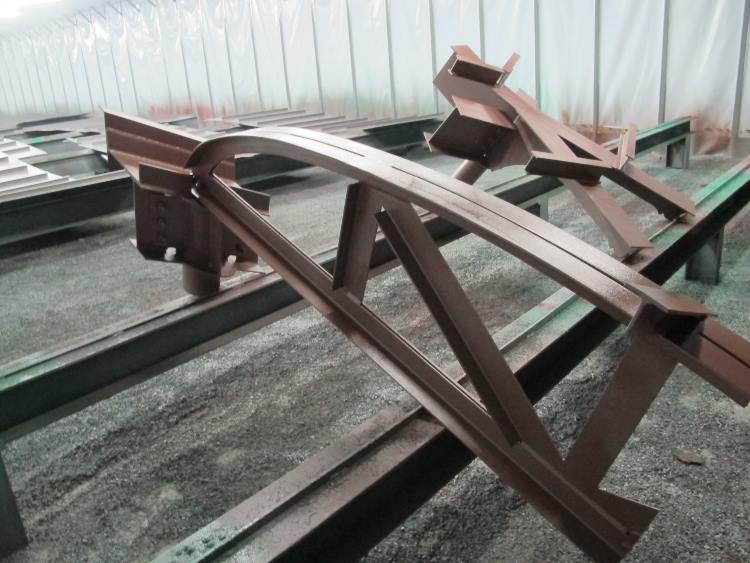
Crusher Station Buildings, Feed&Discharge Conveyor Steel Structures: Box Support Truss

Crusher Station Buildings, Feed&Discharge Conveyor Steel Structures: Conveyor Transfer Tower
Crusher Station Buildings, Feed&Discharge Conveyor Steel Structures: Conveyor_transfer_Tower_12_Conveyor_transfer_Tower
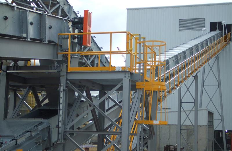
Crusher Station Buildings, Feed&Discharge Conveyor Steel Structures: Custom Platforms

Crusher Station Buildings, Feed&Discharge Conveyor Steel Structures: Gallery Trusses

Crusher Station Buildings, Feed&Discharge Conveyor Steel Structures:
Crusher Station Buildings, Feed&Discharge Conveyor Steel Structures:
Crusher Station Buildings, Feed&Discharge Conveyor Steel Structures:
Crusher Station Buildings, Feed&Discharge Conveyor Steel Structures:
Crusher Station Buildings, Feed&Discharge Conveyor Steel Structures:
Crusher Station Buildings, Feed&Discharge Conveyor Steel Structures:
Crusher Station Buildings, Feed&Discharge Conveyor Steel Structures:
Crusher Station Buildings, Feed&Discharge Conveyor Steel Structures:
Crusher Station Buildings, Feed&Discharge Conveyor Steel Structures: Gallery Trusses

Crusher Station Buildings, Feed&Discharge Conveyor Steel Structures: Support Bents

Crusher Station Buildings, Feed&Discharge Conveyor Steel Structures: Transfer Tower
Crusher Station Buildings, Feed&Discharge Conveyor Steel Structures: Walkways
Why ZHM Huawu Steel Secondary Tertiary Crushing Station Buildings Featuring Four (4) Crushers, Feed&Discharge Conveyor Steel Structures ?
 |
 |
 |
 |
| Reliable and Customized Designs | Cutting Edge Designing Process | Free Online Price System | Easy Bolt-by-number Assembly |
 |
 |
 |
 |
| Over Two Decades of Experience | Value For Money | Unmatched in Quality and Craftmanship | Excellent Customer Service |
Would you like to see more information and images of ZHM Huawu Steel's Secondary Tertiary Crushing Station Buildings Featuring Four (4) Crushers, Feed&Discharge Conveyor Steel Structures ? Visit our Photo Gallery.
HOW CAN WE HELP YOU?
ZHM’s world-class team — together with our raw material suppliers and subcontractors — works to solve your most challenging design, engineering, farbrication or construction issues.
Contact ZHM by telephone at +86 135-8815-1981 (wechat and whatsapp) or send us your questions via email to info@zhmsteelworks.com