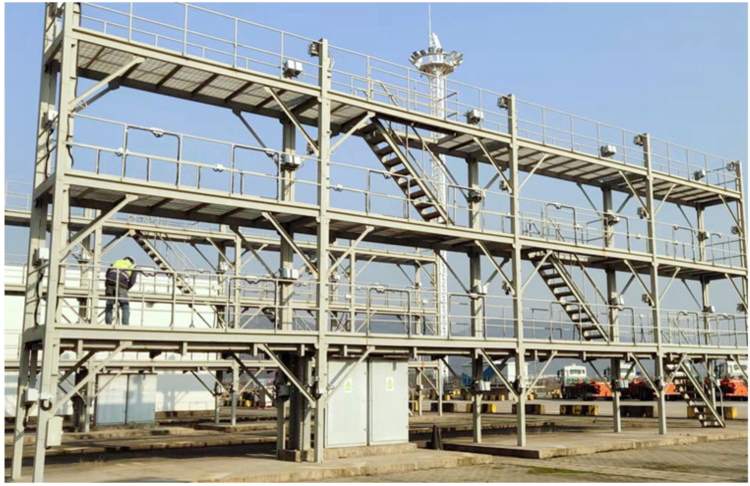
Reefer Rack Foundations Preparation as per EN 1997
Part 1: Arrangement and Geometry
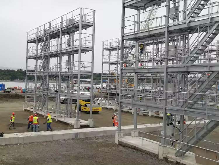
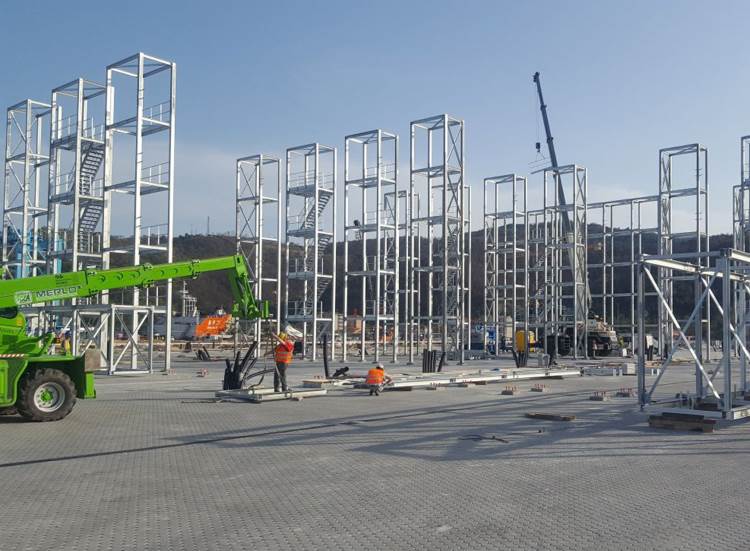
1.1.The foundations for the reefer racks may be single concrete slabs, or localised plinths for each column foundation, shallow foundations or piled foundations, or combined solution with container stacking plinths, whichever is most economical and best suited to the structural requirements.
1.3. Dependend on the choice of foundation type by the Contractor, but where the finished level of the foundation is to be higher than the surrounding pavement level, and is not applicable if combined foundation is selected by the Contractor: Inspection Point
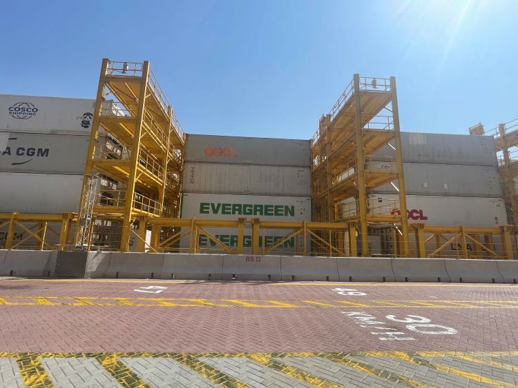
(a) The raised foundation shall not extend more than 200mm of the face of the containers in either direction.
(b) In the longitudinal direction, the raised foundation shall additionally not extend beyond the face of the containers.


Part 2: Design Requirements
2.1. The foundations shall be designed in accordance with EN 1997 and EN 1992, or other approved international standards by the Engineer for shallow foundations and reinforced concrete structures.
2.2. The foundations shall be designed to resist the loads applied from the reefer rack, including potential uplift at some columns from storm or seismic cases if relevant.
2.3. The foundation design shall include, as a minimum, bearing pressure, overturning and flexural effects, for static, storm and seismic cases.
2.4. The holding down bolt arrangement and details shall be designed to ensure there is no concrete breakout failure (or other applicable failure mechanisms subject to the geometry), according to ACI 318M or other approved international standards.
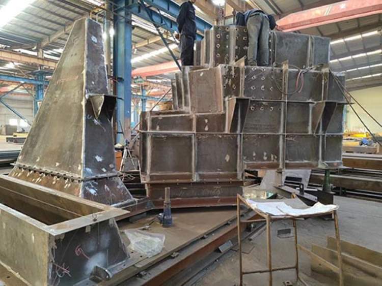
2.5. Holding down bolts and setting out templates shall be supplied by the reefer rack manufacturer and cast into the concrete foundations by the civil works contractor.Inspection Point These items shall be provided in advance of the delivery of the main frame at a timing to be agreed with the Employer and/or the Engineer to suit the overall programme for the Works.
2.6. Post-installed bolts shall not be permitted where foundations are newly constructed.Post-installation shall be limited to retrofitting of existing structures and shall be subject to review by the Engineer. If used, then the structural reinforcement shall be located via non-destructive means or via localised demolition of the cover zone to ensure that reinforcement is not damaged.
2.7. If a transformer and/or switchboard is required at ground level, the foundation shall be designed to accommodate the weight and shall include suitable conduit connections/penetrations positioned to suit the electrical equipment.
2.8. The foundation shall include at least one electrical pit for connection of the LV electrical power cables and communications cables to the wider network. If required, a second pit shall be provided for connection of MV electrical power cables. The pit(s) shall incorporate a drainage detail to prevent it from filling with rain water or ground water. The pit lid(s) shall be designed for the live loads specified in Appendix I “Design Criteria”and shall be manually removable by two (2) persons. Any metallic parts of the pit, including lid frames, shall be connected to the reefer rack earthing system.
2.9. The number, size, bending radius and position of the electrical conduits shall be determined to suit the electrical equipment and cabling, and shall be cast into the foundations. Inspection Point
2.10. The foundation shall include a pit(s) for earthing of the reefer rack and inspection/ testing of the earthing point(s)


Would you like to see more information and images of ZHM’s Reefer Rack Foundations Preparation as per EN 1997 ? Visit our Photo Gallery.
HOW CAN WE HELP YOU?
ZHM’s world-class team — together with our raw material suppliers and subcontractors — works to solve your most challenging design, engineering, farbrication or construction issues.
Contact ZHM by telephone at +86 135-8815-1981 or send us your questions via email to info@zhmsteelworks.com

