Steel Structure Columns in Modern Architecture
Steel Structure Columns in Modern Architecture
Home » Steel Building » Steel Structure Columns in Modern Architecture
Table of Contents
2.Steel structure column foot
3.Composition of H-shaped steel column
3.1.1. Column foot part
(1)The composition of the column foot part
(2) Identification diagram of column base
3.1.2. Steel column with bracket
(1) Composition of steel bracket
(2) Diagram of the bracket
4. Column-beam connection
(1) The composition of the column-beam connection
5.The installation of steel structure columns
Introduction and classification of Steel Structure Columns
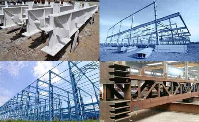
The steel column is the structural component that bears the main vertical load in the steel structure building. Based on their cross-sectional shape, they are classified into solid-web and lattice columns. The solid web column has an overall cross-section, with commonly used shapes being I-beams, typically made of hot-rolled H-beams, I-beams, or welded H-beams. Solid web columns are generally used in light steel structure buildings.
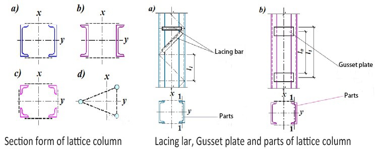
The cross-section of a latticed column is divided into two or more parts, which are connected by lacing bars or gusset plates. This design reduces the amount of steel required, mainly when the column is wide and bears heavy loads. Latticed columns are typically employed in the construction of heavy-duty steel buildings.
The H-shaped steel column is divided into two types the equal-section and the variable-section column. The equal section is typically represented as H (height in mm) × (flange width in mm) × (web thickness in mm) × (flange thickness in mm). The variable section is represented as H (minimum height – a maximum height in mm) × (flange width in mm) × (web thickness in mm) × (flange thickness in mm).
Steel structure column foot
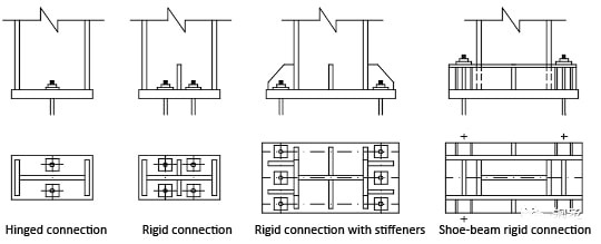
Column foot
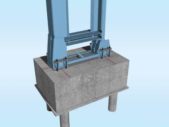
Shoe beam rigid connection column foot
Composition of H-shaped steel column
1. Column foot part
(1) The composition of the column foot part
steel Column foot
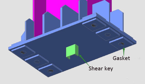
Steel column shear key
Steel column foot
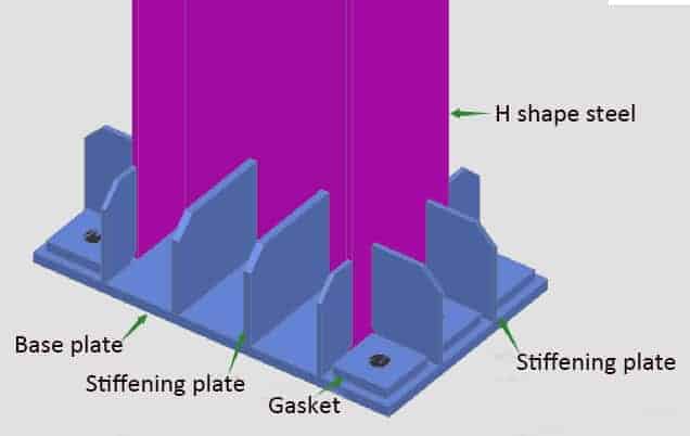
Column foot detail
(2) Identification diagram of column base
From the above figure, it can be seen that the shear key at the column foot is [10 channel steel, with a height of 100mm; the steel plate at the column foot is (500mm970mm28mm); the thickness of the web stiffener is 20mm, and the height can be considered as 250mm. The width is 290mm.
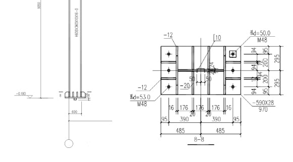
Flange plate stiffeners are divided into two categories, one is perpendicular to the H-shaped steel column flange plate, with a thickness of 12mm, and the other is flush with the H-shaped steel column flange, with a thickness of 16mm; The size is not marked, the general consistency is 20mm thick, M48 is the diameter of the embedded bolt, d=50.0 is the size of the opening on the steel plate at the column base, and the base plate of the anchor bolt can generally take the size of the opening at the column base + 50mm. Therefore, the figure’s pre-embedded bolt backing plate can be considered 100mm100mm20mm.
2. Steel column with bracket
The bracket is welded on the steel column, one side is rigidly connected with the column, and the other is suspended from bearing the vertical load from the crane beam and the crane.
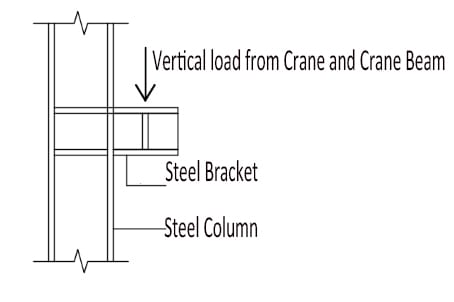
Steel Bracket
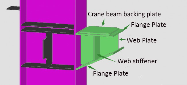
Crane Bracket
At the bracket, some steel columns have wall bracing corresponding to them. The connection between wall bracing and columns requires connecting steel plates on the columns.
(2) Diagram of the bracket
From the above figure, it can be seen that the backing plate of the crane girder is 320 mm 320 mm 16 mm, the upper flange of the crane girder is 16 mm, the lower flange is 16 mm, the web thickness of the middle variable section is 10 mm. Therefore, the size of the variable area is 200 mm to 390 mm. The web stiffener is 11 mm165 mm175mm.
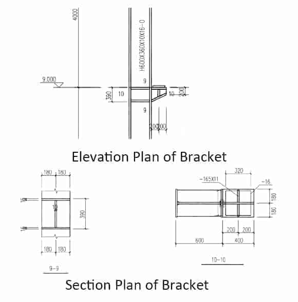
Crane Bracket
3. Column-beam connection
(1) The composition of the column-beam connection
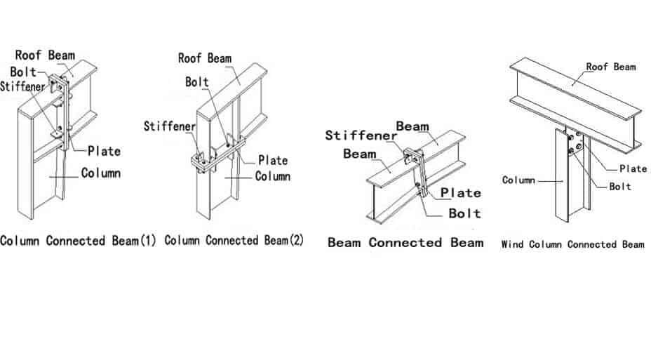
Connection Detail
The installation of steel structure columns
The first step is to directly hoist the steel column by the crane and fix it with the embedded bolt through the hole reserved in the steel plate at the base of the column.
The second step is tighten the pre-embedded bolts and fix the nuts.
Steel Column installation
- Pre:None
- Next:Steel Structure Design Princip 2024/4/27

