
Design of Bailey Bridge Load Capacity Test Scheme
2024/8/31 view:
Design of Bailey Bridge Load Capacity Test Scheme

Project Overview Waiting for Bailey Bridge Load Capacity Test
Design of Bailey Bridge Load Capacity Test Scheme
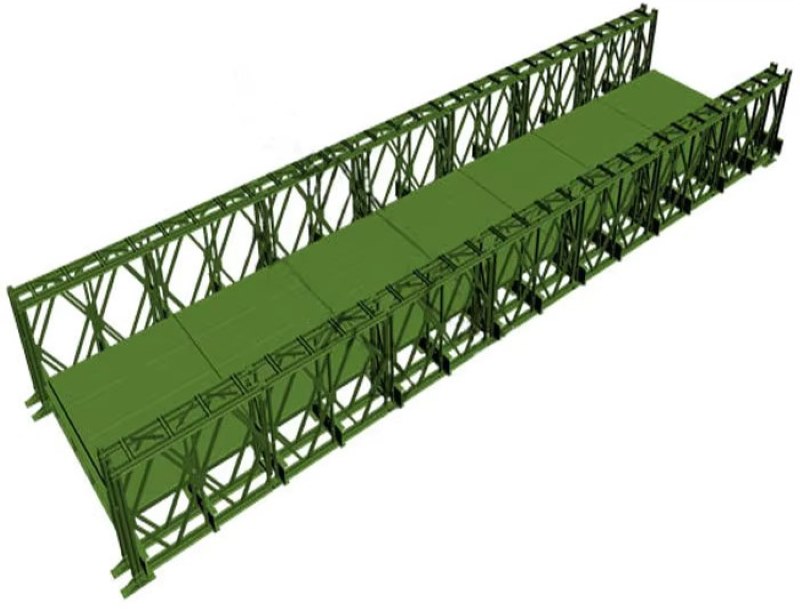
Bailey bridge project overview
Technical Standards for the Design of Bailey Bridge Load Capacity Test
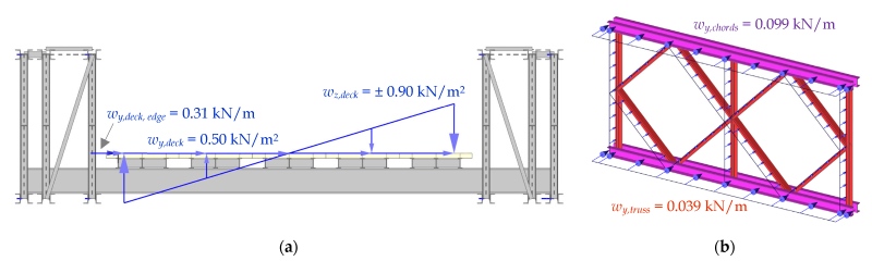
- Actual width of bridge deck: 0.73m Bailey beam + 0.17m curb + 4.2m carriageway + 0.17m curb + 0.73m Bailey beam = 6m
- Design load of Bailey Bridge: Chinese Bridge Load Standard Automobile-10 class, trailer-120
- Longitudinal slope: 0%, cross slope: 0%
-
Preparation before Bailey Bridge Load Capacity Test

The test vehicle travels at a constant speed along the bridge deck. In this process, the tester is responsible for collecting the settlement value and deflection of each test section.
- Situation 1: The test vehicle drove over the test Bailey Bridge at a constant speed of 5km/h;
- Situation 2: The test vehicle drove over the test Bailey Bridge at a constant speed of 10km/h;
- Situation 3: The test vehicle drove over the test Bailey Bridge at a constant speed of 15km/h.
Specific Steps of Bailey Bridge Load Capacity Test
 |
 |
| Bailey Bridge truck drive load capacity test is underway | Bailey Bridge load capacity test is underway at Constant Speed |
- Before starting the test, relevant personnel should measure and record the test point located at the center of the largest span of the Bailey Bridge. The deflection value measured before opening to traffic is the deflection before load. When the deflection before load does not exceed the allowable value, proceed to the next step.
- For safety reasons, a small unloaded vehicle passed the Bailey Bridge several times. Before opening to traffic, relevant personnel set up a measuring point at the center of the maximum span, and when small unloaded vehicles pass several times, measure whether the bridge deflection has excessive changes and whether it exceeds the allowable value. When there is an excessive change or beyond the allowable range, the corresponding treatment should be carried out, otherwise, proceed to the next step.
- 80% standard load test. The vehicle is loaded with 80% of the load of the design standard Bailey bridge, and the vehicle is driven to the center of the maximum span to stop, and the deflection and deformation values of the measuring point are recorded. If the measured deflection does not exceed the maximum allowable range, proceed to the next step.
- Standard load test. Record the corresponding value at the center of the maximum span of the vehicle whose weight is the design-approved load. This value is the deflection under load. If the measured deflection does not exceed the allowable value, proceed to the next step.
- Overload test. Load the vehicle with 120% of the design standard approved load weight, park the vehicle at the center of the largest span of the Bailey Bridge, and record the relevant data.
- Pre:None
- Next:How To Construct A Bailey Brid 2024/8/31